The following describes a programmer for Silicon Laboratories (SL) processors (chips) that use the C2 programming protocol. The protocol is described in SL Application Note AN127, "Flash Programming via the C2 Interface."
The programmer was developed when the author migrated to Linux from a Windows development environment. In Windows, chips were programmed with the SL Integrated Development Environment (IDE) and the SL USB Debug Adapter. This software and hardware cannot be easily migrated to a Linux environment.
The programmer uses an interpose processor (IPP) that connects between a Host PC and the chip to be programmed, the Target. The Host exchanges data with the IPP via a serial link and the IPP programs the Target chip with its C2 signal connections. Because only two connections and ground are needed for the C2 link to the Target, in-circuit programming is greatly simplified.
Thus, programming data is transfered from the Host to the IPP which, in turn, downloads the data to the Target chip using the C2 protocol. The IPP was initially built using a C8051F300 chip mounted on a DIP-format carrier board (a BOBZ AGEN board). A second IPP was also built using an inexpensive ($10) SL Toolstick Daughter card for a C8051F850 chip. Besides one of these processor boards, only a handful of inexpensive parts are needed to build the programmer.
The C8051F300 and C8051F361 chips are now used for most BOBZ products. Some applications are also being migrated to the new C8051F850 chip. The programmer handles these chips and most of the C2-capable chips given in Table 10 of the C2 application note. Other supported C2 chips include the 'F31x, 'F33x and 'F41x chip families.
Page ii
(BLANK)
Page 1
Page 2
Page 3
As described above on the title page, the PROG C2 programmer consists of a Silicon Laboratories (SL) chip programmed to implement most of the C2 programming protocol, as described in the SL Application Note AN127, titled "Flash Programming via the C2 Interface."
The chip acts as an "InterPose Processor" (IPP) that interposes between the Host PC, the Host, and the chip to be programmed, the Target. The IPP connects to the PC's serial port to talk to the Host. The IPP also connects to the Target's data and clock lines (C2D and C2CK) to program it using the C2 protocol. Thus, programming data is transmitted on a serial link from the Host to the IPP and the IPP uses this data to program the Target with a three-wire C2 connection. The IPP can read the Target chip and the send readout data back to the Host for verification.
The myforth 8051 programming software was used to develop the programmer applications. The application for the 'F300 chip is named PROG and the application for the 850 Toolstick processor is named PROG-850. The programmer software runs under Gforth, a free Forth system that is widely available for most Linux distrubutions.
Presently, the programmer can only be used comfortably in a Linux environment. It could be readily adapted to a Windows environment but, not to much purpose considering the availablity of the SL IDE for Windows.
In its most basic configuration, the programmer consists of a system board (i.e., an AGEN or 850 Toolstick board), a three-wire serial connection to the PC Host and a three-wire connection to the Target programming pins.
Why not use the myforth Bootloader? -- The myforth bootloader is capable of downloading a program image to flash. This capability wasn't used for several reasons. One drawback is that the bootloader image needs to be initially programmed on the Target using the SL IDE. But, thereafter, the Target can reprogram its flash program memory via a serial connection to the Host. Although this doesn't eliminate the need for the SL IDE and Debug Adapter somewhere in the chain, this is not a compeling reason for not using the myforth bootloader for programming.
The serial port problem -- Unfortunately, the myforth bootloader has not worked well with modern PCs lacking hardwired serial ports. Most PCs now use a USB to serial converter to provide a serial link. We have found that these have not performed reliably (or at all) with the single-character binary handshaking used by the myforth bootloader. The main problem appears to be bootloader timeouts or hangups due to delays in the adapters. This is discussed in the Implementation section and is the main justification for using a standalone C2 programmer.
The programmer works with both hardware serial ports and USB to serial adapters, although programming throughput often suffers when using the USB to serial adapters. As noted above, this is discussed in more detail in the Implemention section.
Other considerations -- Another argument in favor of eliminating the dependency on a bootloader is that a standalone programmer does not require the re-mapping of the 8051 jump vectors (i.e., for the bootloader). Further, it eliminates the need to initially load a bootloader on the chip with the IDE. The programmer can write Target images containing the bootloader, however.
Page 4
Before launching into the C2 programmer project, it may be useful to consider several alternatives to programming SL chips with Linux that were investigated.
EC2DRV -- The first alternative was to use the "EC2DRV" software for Linux. It promised to allow the use of the SL USB Debug Adapter. Being a Linux newbie, the author could not get this (somewhat older) software to work, although it is likely that a more experienced Linux programmer could make it work.
Windows Emulator -- Another alternative was to use the Wine (or some other) Windows emulator to run the Windows IDE with the USB Debug Adapter. Although some thought this might work, others thought that the USB support for Wine was limited. It was difficult confirm whether or not Wine would support the SL programming environment. Again, being a Linux newbie, this appeared to be more of a research project than a straightforward solution.
Also, the myforth manual is in the process of being re-written to be Linux-centric. Describing the chip programming procedure with the requirement of first installing Wine seemed like an unneccessary complication for programming with myforth on a Linux Host.
Page 5
The programmer features include the following:
For systems using USB to serial adapters, the readout times are approximately the same. Programming, however, may take as long as 35 seconds for an 8K image. The programmer detects empty programming blocks and skips over them to reduce programming times for chips with small programming images.
Page 6
The AGEN system board used for the IPP programmer measures approximately 3/4 by 7/8 inches (~ 2 by 2.5 cm). The first page of this manual shows the programmer and Target modules mounted on a Parallax 3x5 inch prototyping board. The 850 Toolstick daughter card is approximately 2 by 2 inches (~ 5 by 5 cm), as shown in later sections.
Schematic 1 shows the AGEN-based PROG programmer (IPP) and its typical connections to a Target chip. Note that only three wires are needed to connect to the Target.
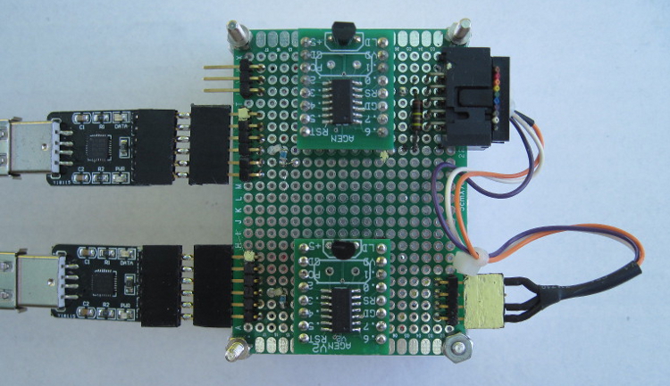
As shown by the schematic and Photo 1, signal connections for power and serial communications are provided on a 6-pin single-row header located along one of long edges of the board.
On the opposite edge, a 10-pin shrouded IDC header provides a C2 connection to Silicon Laboratories Target Boards or in-circuit programming for application boards. The Target Boards are connected with a 10-pin ribbon cable and application boards are connected with a 3-wire programming adapter (10-pin socket to 4-pin in-line header).
Page 7
The '300 chip version of the programmer is built around an AGEN module that does not have an external crystal installed: the AGEN module uses the 'F300 chip's internal 24.5 Mhz oscillator.
The chip can be reprogrammed using the Silicon Laboratories (SL) Debug Adaptor and Integrated Development Environment (IDE) hosted on a Windows PC. You can also clone a new or updated module with an existing PROG or PROG-850 programmer. We recommend the purchase of two PROG boards to allow for updates and for initial checkout of the programmer.
The '850 Toolstick version of the programmer can be reprogrammed with a Toolstick adapter and the Integrated Development Environment (IDE) on a Windows PC. Another 850 Toolstick programmer or AGEN-based programmer can be used to program the Toolstick via the C2 programming connection. These "program the programmer" connections are shown in the schematics.
Page 8
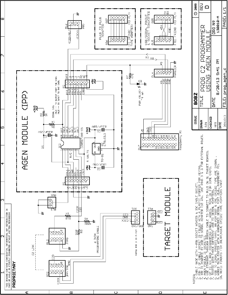
Schematic 1 -- AGEN Based C2 Programmer
Page 9
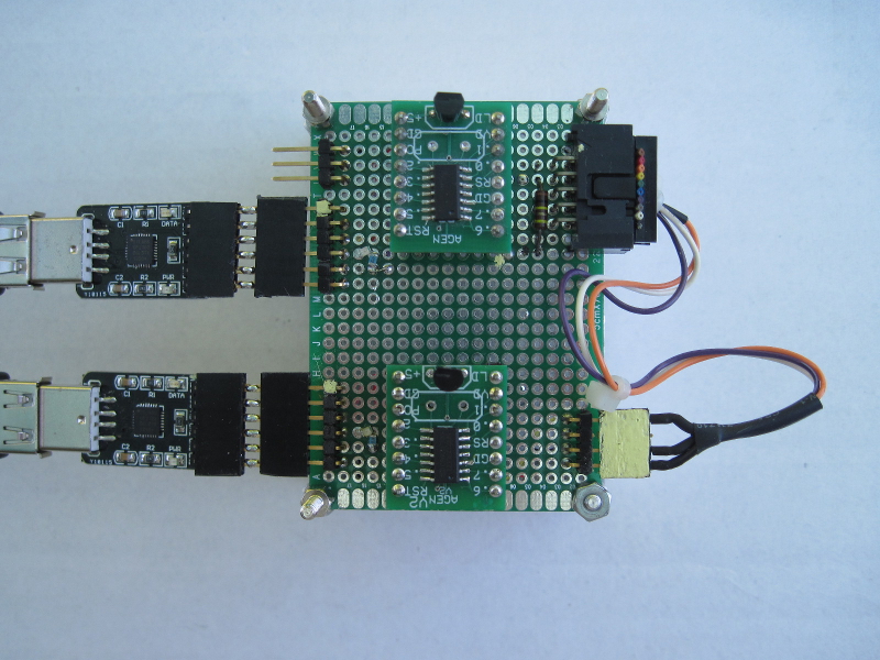
Photo 1 -- AGEN Based Programmer (top) and Target (bottom)
Page 10
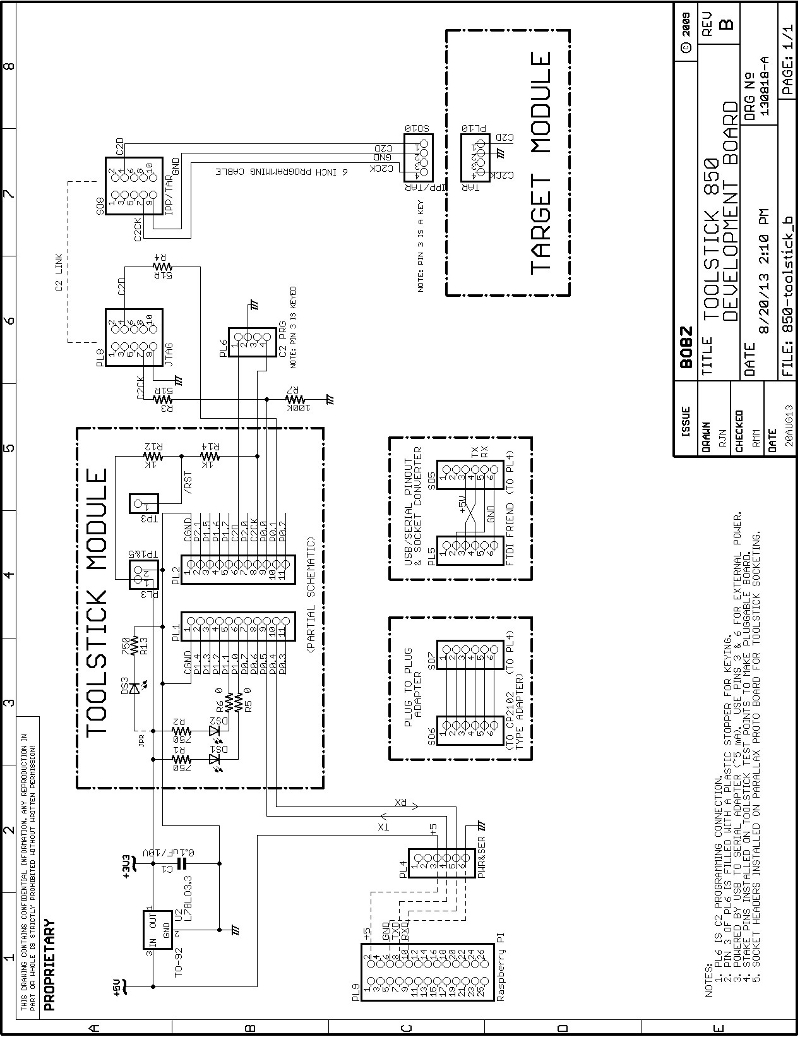
Schematic 2 -- 850 Toolstick Based C2 Programmer
Page 11
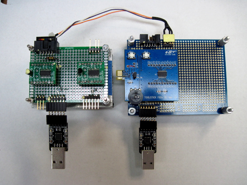
Photo 2 -- 850 Toolstick C2 Programmer Connected to AGEN Programmer
Before proceeding, we recommend downloading the programmer schematics as a zip file and print them out. The downloadable schematics are high resolution files that, when printed out, are easier to read than the schematics embedded in the body of this manual. Also it is easier to reference the printed schematics than to frequently page back to them.
Page 12
The following presents the programmer design objectives:
Page 13
To use an AGEN or 850 Toolstick module as a programmer, the following are required:
Because of the low power requirements for both versions of the programmer, most USB to serial adapters can easily power the programmer.
The schematics show this connection made with a 6-pin right angle header at the edge of each programmer board. The pinout of this serial/power connector, PL4, is designed to match the pinout one of the popular and inexpensive adapters sold on EBay, but can be adapted to other units, as shown in Schematic 1.
Another easy way to get a power connection to the programmer board is to use a socket connection on a breadboard jumper wire to connect to a pin on the serial/power connector. The other end of the jumper can connect to a pin on a USB to serial adapter or to a pin on a processor board's I/O connector. This kind of connection for a Raspberry Pi is shown on both schematics.
Because USB serial adapters or processor boards may not supply the 3.3 Volt power needed for the programmer chips, the programmers were designed to use 5 Volts.
In the case of the AGEN module, a 3.3 Volt regulator is mounted on the module. Five Volt power can be applied as shown in Schematic 1. Five Volt power from an adapter, power wart or processor board should be connected between pins 3 (+5 Volts) and 6 (ground) of the serial/power connector.
![]()
In the case of the 850 Toolstick module, a separate 3.3 Volt regulator is required. Many USB to serial adapters provide a regulated 3.3 Volt output that can be connected to one of the unused pins of the 6-pin serial/power connector. For example, the adapter we commonly use provides this on pin 1.
Although Schematic 2 does not show this connection, it can be easily added. Because the 850 Toolstick programmer draws approximately 5 milliamperes, the adapter's on-board regulator shouldn't be challenged unless it is also connected to other devices.
A separate inexpensive regulator supplies the Toolstick, mostly because five Volt power is more universally available than 3.3 Volt power. Also, putting the regulator close to the Toolstick is a good idea. The connections shown in the schematic for the Raspberry Pi use its five Volt output and the separate 78L33 voltage regulator (the regulator costs about $0.25).
Page 14
The serial data link can be provided by a USB to serial adapter or by a direct connection to a hardwired TTL-level serial port (e.g., as shown for the Raspberry Pi). Connection to a hardwired port that operates at true RS-232 voltage levels will require a TTL to RS-232 adapter. These are inexpensive and commonly-available. These are discussed and shown in the manual for the BOBZ DCON product.
The data directions and designations for transmit (TXD) and receive (RXD) can be confusing because the perspective it is not often clear (e.g., is this to or from the PC or the chip?). To help clarify this, the schematic provides direction arrows and notes. Also, many USB to serial adapters have arrow designations. If your connections do not work, you might try reversing the connections. Although we are obligated to warn that this may damage some types of hardware, we have done this on several adapters and on the Raspberry Pi without damage (your mileage may vary).
For now, the serial data link operates at 19.2K baud. Assuming you are using minicom, we suggest you bring it up as root in the configuration mode (i.e., "sudo minicom -s"). This will allow you to set the com port and baud rate and save it in the default file. You can also specify that the current configuration be saved as a configuration file. These are named "minirc.xxx", where the "xxx" is a name you supply. Configuration files are normall stored in /etc/minicom and can be furnished as a command line parameter at startup (e.g., "minicom sb1" for a configuration file named /etc/minirc.sb1 specifying /dev/ttyUSB1 as the serial port).
Serial device mappings vary between Linux distributions but, using a USB to serial adapter, our large PC maps the first com device as /dev/ttyUSB0. The Pi has only a single port which maps to /dev/ttyAMA0. You can change these in minicom and save as the default or custom startup file, as above, so that you come up on the right device.
To find what devices you system has mapped at startup, use something like "dmesg | grep "ttyUSB" or "dmesg | grep "tty" .
Once you have a power and a serial connection to the programmed processor, we suggest changing to the programmer's project directory (e.g., ~/myforth/projects/prog-850) and executing the "p" command file (e.g., "./p") to see if the chip is alive. Without a Target connection, the operation will abort but it will still provide serial output to verify the connection.
Page 15
The next step in building the programmer is to wire the C2 connections to the Target programming connector. This connector is a 10-pin, right-angle, shrouded IDC plug. Although there are only three connections needed to connect to the Target chip, using this connector provides a direct and convenient connection to a 10-wire ribbon cable between the programmer and a SL Target Board. Connections to a chip that is in-circuit on an application board require a custom adaptor cable, as shown on Schematic 1 and Schematic 2, and described below.
The connections between the chip modules and the 10-pin programming plug are isolated with 51 Ohm resistors. This is the smallest value on hand that satisfied the requirement to isolate the programmer from the Target board.
The SL datasheets for the 'F300 and 'F850 chips specify that a maximum of 100 mA can be drawn from any pin. Assuming that the Target side may be driven low (or shorted), the current limiting provided by the resistors is (3.3 Volts)/(51 Ohms)=65 mA.
Although larger resistors may work, it is prudent to minimize any programming signal rolloff and delay due to cable, chip input and board trace capacitance. One might think that the connection to the Target's C2CK line does not need protection because it is wired to the Target's reset pin. Careful reading of the datasheet reveals that the reset line is internally driven low during a reset sequence.
We wired 0805 surface mount (SMT) resistors between proto board pads and connected them to the module and connector pins with wire wrap wire. It is probably more convenient to use leaded resistors, but it only takes a little care to ensure the SMT resistors will fit between the pads without shorting underneath.
We suggest wetting the pads with solder before placing the SMT resistors and then holding them in place with tweezers, at a slight angle between the pads, while applying the soldering iron alternately to the pads and resistor ends. Once in place, wire wrap wires can be soldered to the wetted pads. We recommend wetting the wire wrap ends before soldering them to the pads. Use of solder paste is not necessary, especially if the solder is fine enough, but solder flux on the pads and chip ends can help reduce the time that the iron must be applied to the connection.
To allow automatic detection of the Target, a 100K resistor is wired between ground and the connection to the Target's C2CK signal. To detect the Target, this line is turned around to be an input to see if the Target's reset voltage is present. The 100K resistor ensures that, in the absence of a Target, the line is always pulled low.
Page 16
If you have a way to program the programmer using another C2 programmer, you may want to install a programming connection for the programmer.
Normally you will need only one programmer. The AGEN based programmer shown in Photo 1 does not have a connection for programming it with a second programmer. This is because the initial programming was done on a Windows system. Also, after the basic programmer was working, upgrades were performed by programming the new version on the Target and swapping between programmer and Target sockets.
As shown in Photo 2, the 850 Toolstick based programmer does have a four-pin programming connection. This is because it was initially developed using the 300 programmer. Suit yourself: both schematics show the programmer programming connections (PL6).
The programming connection consists of a four-pin right-angle stake pin strip. One pin is cut off to key the programming cable. Which pin to cut off is determined by the position of the keyed socket pin. Refer to the programming cable section below for keying instructions.
Clip off the stake pin that corresponds with the keyed pin. Wiring the connection is simple. Ground the pin remaining between the two end pins. Wire pin 4, the pin next to the cut pin, to the reset (C2CK) pin on the chip. Wire pin 1, the pin next to the grounded pin, to the C2D pin on the chip.
Page 17
Two different programming cables may be required, depending on your development environment. In many cases, only one cable is needed.
If you are developing with one of the SL Target Boards (TBs), the programming cable consists of a ten-wire straight through cable with sockets on each end. This cable connects between the 10-pin programming connector on the Target Board and the corresponding 10-pin plug on the programmer. The length should be initially limited to six inches, although a length of eight inches worked for all of the Target Boards we tried (i.e., 'F300, 'F310 and 'F336 TBs).
A custom cable is required for development with application boards, where the Target may be in-circuit with only a 3-wire programming interface. The wiring for the custom C2 programming cable is shown in both schematics.
One easy way to make this cable is to first press a ten pin socket onto a six inch piece of 10-wire ribbon cable. Alternatively you can cut an end off of an existing cable. Because pre-made cables are commonly available, this is perhaps the easiest way to start.
Next, strip out the wires for pins 4, 7 and 9. These are usually color coded as yellow, violet and white, respectively. You can cut off the other wires close to the socket body, but we recommend leaving a small group of wires sticking out to provide a small pull tab. This makes it easier to pull the socket out of the shrouded (keyed) pin header.
Trim the three remaining wires to a length of 6 inches. These solder to the four- pin socket header. Prepare the header by cutting off one of the two inner pins. This is pin 3 and is used for keying. To key the header, insert a non conducting nib into the socket. The traditional way to do this is to insert the small end of a flat toothpick and break it off flush with the connector edge. Small plastic inserts are sold for this purpose, but are not readily available.
To ensure the header connections are not exposed, push some heat shrink on to each wire before soldering it to the socket pins. Thus, the heat shrink can be slid down over the socket/wire connection and shrunk to provide a neat insulated connection. You may also want to slide a larger piece of heat shrink over all three wires before wiring. This can be slid down on top of the three wires to provide some strain relief.
The easiest way to connect the socket header to the wires is to first tape the header down flat on a work surface and wet each pin and each wire with solder. Solder the white wire (the pin 9 ground connection) to the only remaining inside pin. Solder the yellow wire to the outside terminal next to the white wire. Solder the purple wire to the remaining outside pin (next to the keying pin).
The most common mistake made in assembling a ribbon cable for use with a shrouded (keyed) pin header is accidently reversing the cable when pressing it on the socket. To avoid this, we recommend performing a continuity check between the brown wire and pin 1 of the header. Pin one is identified by a small triangle molded into the shroud. For cables that are not color coded, the first wire is usually identified with a red or black stripe. If coding your own wire, use a permanent marker to put a stripe on the wire that connects to pin 1.
Page 18
The programmer commands and capabilities can be grouped as follows:
The commands outline above can be executed interactively or as part of a bash shell script (herein called a command script). By integrating several primitives, programming operations can be bundled to provide ad hoc high-level functions that can be executed with a single command.
The prime example of this high-level functionality is the "pc" command script that is used to program the Target chip, read out the programmed chip and verify the programming, all in a single command. Other commands included within the "pc" script include checking for the presence of a Target, reading out its ID and revision and reseting both the IPP chip and the Target. The command script also adds date/time stamping for each operation and saves the programming results in a local file.
Other command scripts allow for interactive use of the programmer and performance of common operations such as chip cloning.
Page 19
The operational capabilities described above are implemented by combining the functionality available in Linux, Gforth and myforth. The role of each is described in following sections with supplemental notes in the Implementation section.
Linux -- The programmer is designed to operate in a Linux environment. The current system was implemented using the Debian distribution but should be easily adaptable to other distros such as Ubuntu which is Debian based.
The rationale for using Linux is that we have recently migrated our real-time work to Linux because Windows was a less suitable environment for what we wanted to do. The current project is the first Linux project and was necessitated by the apparent lack of SL programming capabilities on Linux. Also, the motherboard on our Windows PC died in a puff of smoke. Hello Linux!
One reason to use Linux was to take advantage of the inexpensive functionality provided by Linux-based products such as the Raspberry Pi. One direction for BOBZ products is to provide simple serial peripherals that will work with processors such as the Pi and the BeagleBone Black.
The availability of Debian (or closely related) distributions on many of these products is also convenient. To develop new products using our existing environment of myforth and SL chips requires a convenient way of developing new products without having to use a Windows machine for programming. The loss of productivity in going back and forth between two machines is unacceptable (as this project demonstrated).
One of the advantages of using Linux is the availability of Gforth on a wide variety of systems, spanning desktop PCs to small machines such as the Raspberry Pi. As Gforth is the basis for the myforth compiler and tether, this was essential.
Another important advantage of the Linux OS for a project of this type is the availability of many powerful system tools. The most important of these is the ability to use bash shell scripts to control the operation of Gforth and to provide system-level utilities such as I/O redirection, directory and file manipulation and other operations that do not make sense to do under program control.
Although the Linux learning curve was steep, once the basics were mastered, development became much easier and faster than in a Windows environment.
Page 20
Gforth -- Although Gforth was essential for using myforth on Linux, several features of Gforth in a Linux environment made the programmer much easier to develop. In fact, Gforth seems to be designed for such an environment. The ability of Gforth to compile source and execute commands from command line parameters makes the writing command scripts much easier. Although this capability is also available on Windows, the flexibility and functionality of bash scripts is much greater than with batch files, allowing complex operations to be performed in conjunction with Gforth. Gforth also supports input and output from standard system files such as STDIN, STDOUT and STDERR.
The primary disadvantage to using GForth on this project was a deficiency in the Word used to check for the availability serial characters. This formerly-working capability was evidently broken in a recent release and presently has to be corrected by recompiling the latest source from a git archive. This is discussed in more detail in the Implementation section.
For experienced Linux hands, fixing the Gforth serial problem is not a particularly onerous task. In fact, our "big" Linux machine was remotely updated by Bill Kibler (this site's host). Bill also provided step by step instructions for the Raspberry Pi and BeagleBone Black (see his Blogs at this site). But, we did not want to develop a project that requires an update of Gforth.
Accordingly, the programmer uses only "blocking I/O" for responses from the IPP. With blocking I/O, the Host waits forever for a character, if necessary. This limitation has not caused any major development problems and allows the use of any Gforth version that is commonly available (e.g., that for the Raspberry Pi).
myforthThere is little to say about myforth except that it was originally designed to operate in a Linux environment. Functionally, myforth is used to implement the Interpose Processor (IPP) that "interposes" between the PC Host (Host) and the chip to be programmed (Target). The IPP uses Charley Shattuck's standalone interpreter (~450 bytes) to execute commands sent from the Host by a Gforth program.
The design approach for the programmer is somewhat different from other BOBZ projects using a standalone interpreter on the chip connected to the PC. Interactive commands are not sent directly to the IPP by the user. Gforth controls the serial port and issues commands as part of executing a Gforth Word (usually one of the same name as that defined in the IPP).
The final result is that the IPP does not do very much but issue C2 commands, manage buffers and report errors. The IPP program is only 3.1K bytes, including interrupt vectors and a few hundred bytes of on-chip dictionary entries.
Page 21
The following describes the primary programmer commands. There are a number of other commands that the programmer can execute that are not specifically described but may be mentioned as they relate to primary commands. All programmer commands are listed in the Help menu and the Utilities menu. These menus are displayed with the "h" and and "u" commands, respectively.
The brief descriptions provided in these menus are, hopefully, sufficient to understand their purpose and operation. For further understanding of how they work, refer to the source code.
The following not only describes the functions of the various commands but also provides some detail on how they are implemented. High level implementation requirements and details are described in more detail in the Implementation section and in the source code.
There are two ways of implementing commands. The first method directly invokes a command by executing a Gforth routine (Word). The second method issues a command by calling a command script.
The the most-used command is the "pc" command which programs the Target, reads it back and compares the Target programming with the chip programming data. This command is implemented using the second "command script" method: it combines several programmer primitives within a command script, along with system commands to control output and adds system information (e.g., date & time) to the results file. Many of the primitives used in the command scripts are introduced in the "pc" command Section. The direct primitives are also described individually in later sections.
Page 22
The "pc" command is the primary command used to program a Target chip. It is implemented as a command script. A copy of the "pc" command script resides in each of the user's project directories and is executed from that directory during application development.
The "pc" command can be executed by entering "./pc" at a console prompt. The "./" part of the command tells the shell to look for the command script in the current working directory. Because the "pc" command is so commonly executed, we advise creating an alias for this command and putting it in the .bashrc (or the .bash_aliases) file in your home directory. The alias definition is: alias pc='./pc' .
The contents of the pc script are shown in the inset below. The script copies the binary image of the compiled application, chip.bin, to the programmer's directory as target.bin . At startup, the programmer reads target.bin into a "chip" buffer and uses this buffer image to program the Target.
Note: compile your myforth application (e.g., using "./c") just prior to issuing a "pc" command to ensure that the latest version of your application is programmed into the Target. You may also want to define an alias for the "./c" command.
# pc -- program chip  -- 10Aug13 rjn
#
# put this script in your project development directory
#
# set -x
#
declare -x PROJ="/home/bob/myforth/projects"
cp ./chip.bin ${PROJ}/prog/target.bin
# cp ./chip.bin ${PROJ}/prog-850/target.bin
echo "Start PROG Programming Session: " > ./pc.txt
date >> ./pc.txt
echo "PLEASE WAIT: programming and verifying Target chip"
${PROJ}/prog/pcx >> ./pc.txt
# ${PROJ}/prog-850/pcx >> ./pc.txt
# date '+%T' >> ./pc.txt
cat ./pc.txt
After copying the programming file, the pc script sends startup text to a file in the current project directory, named pc.txt . This file is populated with other programming status information and eventually displayed to show the results of the current programming session.
After writing the startup message to the status file, the pc script calls another script, pcx, in the programmer's directory, that does the actual programming. Lastly, the pc script displays the pc.txt file to show the results of the programming.
Note that the results of the last programming session are always available in the pc.txt file. To display the programming results, execute "cat ./pc.txt" at the terminal's prompt.
Page 23
To understand how the "pc" command is implemented, refer to the inset below that shows the contents of the pcx command script.
# pcx -- PROG C2 programmer -- 17Aug13 rjn
#
# calls Gforth -- executed by "pc" command in user's project dev directory
#
# set -x
# declared exportable in pc script:
# declare -x PROJ="/home/bob/myforth/projects"
#
cd ${PROJ}/prog
# cd ${PROJ}/prog-850
/usr/local/bin/gforth-0.7.9-20121007 \
        -e "fpath path+ ./ " \
        -e " 1 value com? " \
        -e " 19200 value current-baudrate " \
        ./serial-linux.fs  ./job.fs  \
        -e " open-comm  read-chip .chip-size  cr rst" \
        -e " cr cr v .(  C2 Programmer: enter h for help)" \
        -e " cr ?target space i" \
        -e " cr p  cr g cr diff cr .fin  tr bye "
# use this line instead of the one above for buffered programming:
#       -e " cr d  cr g cr diff cr .fin  tr bye "
The first line of the pcx script changes the working directory to the programmer directory. The next line calls Gforth. Following lines are continuations of the Gforth command line. The continuation lines starting with "-e" are commands for Gforth to execute at startup. The lines consisting of file names specify source code to be compiled by Gforth. Here is a breakdown of what each of the lines do:
Page 24
Photo 3 shows the results of programming session after the above commands have been executed.
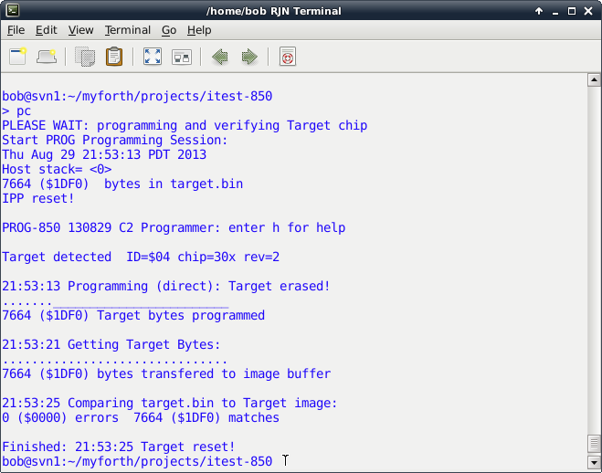
Photo 3 -- Status Screen for a Programming Session
On the results screen, note the following:
Page 25
The "p" command is used to directly program the chip. It is defined as a Gforth command and can be executed interactively or as part of a command script, as described in the "pc" Section above.
There is also a "p" command script to start up the programmer in interactive mode. This is a bit confusing at first, but becomes more natural with use -- the command script invokes the standalone programming mode in preparation for using "p" command to program the chip.
The inset below shows the contents of the "p" command script.
# PROG C2 programmer -- 19Aug13 rjn
#
# set -x
/usr/local/bin/gforth-0.7.9-20121007 \
        -e "fpath path+ ./ " \
        -e " 1 value com? " \
        -e " 19200 value current-baudrate " \
        ./serial-linux.fs  ./job.fs  \
        -e " open-comm  read-chip .chip-size  cr rst" \
        -e " cr cr v .(  C2 Programmer: enter h for help)" \
        -e " cr ?target space i tr"
The script given above is similar to the one used for the "pc" command. It starts up Gforth, compiles the programmer application, initializes serial communications, reads the programming image, resets the IPP, displays the current revision, checks for the Target and reads out its ID information.
The main difference between the scripts is that the "p" script does not perform any programming, readout or verification. More importantly, it does not exit from Gforth: it is left available for directly executing programmer commands. Typically, the first direct command executed after startup is the "p" command.
Photo 4 shows the startup screen produced by the command script in the inset above.
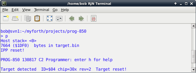
Photo 4 -- Startup Screen for Interactive Programming
Page 26
Photo 5 shows the results of executing the "p" command interactively. The results are identical to those obtained with the "pc" command but without readout and comparison.
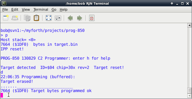
Photo 5 -- Interactive Programming Session
The interactive execution of the "p" command is seldom used by itself for interactive programming. It is normally used in conjunction with other commands. For example, after programming the Target, the "g" command can be executed to get the Target image, followed by the "save-image" command to save the Target image in the target.img file.
For now, saving the Target image can only be done interactively. But, it is easy to edit the "pc" command file to automatically save the image after every programming session.
Another reason to program interactively is to use other programming commands. One of these commands is the "d" command. It programs the chip by buffering the programming blocks on the IPP. The "d" command was initially coded so that programming would be independent of the baud rate. It was later found that, at speeds up to 19.2K baud, the Target could be programmed directly. At higher baud rates, edit the pcx script to use the "d" command.
When using the "d" command with the 'F300 programmer, note that there are a larger number of "." indicators that indicate a block has been programmed. This is because the buffer size for the 'F300 chip is 64.
The normal block programming size for direct programming is the maximum number of bytes allowed for a C2 block program command, 255 ($ff). The 850 Toolstick programmer uses its on-board XRAM cells to provide a larger 255 byte buffer.
The XRAM is internal static ram mapped as external ram. The "d" results for the 850 programmer looks identical to those for "p" command. Note that the programming text indicates whether or not direct or buffered programming is being performed.
Page 27
The "g" command gets the contents of the Target chip. Normally, the command is used by the "pc" script to get the Target contents for verification. It can also be used during interactive programming to get and save a Target image. Both of these uses are described in previous sections.
When the "g" command executes, it saves the bytes downloaded from the Target in a Target image buffer. This buffer is used by the "diff" command to compare against the contents of the programming buffer. It is also used by the "save-image" command to write a Target image to the target.img file.
The "f" command is similar in operation to the "g" command but it performs a buffered read of the Target. The "f" command is of limited usefulness because buffering is never required on output from the IPP to the Host PC. Buffering is useful only on input and only if the Host transmits characters faster than the programming algorithm can handle. Programming an entire block takes just over 2 milliseconds, or approximately two character intervals at 9600 baud.
Because of the questionable usefulnees of the "f" command, it is not available on the 850 programmer.
It is sometimes useful to directly examine the Target image buffer. One such use is to examine bytes for ASCII-coded messages such as the program name and revision. We commonly embed the program name and rev (date) near the start of the first flash code block. For the 300 and 850, this is near $233, just after the interrupt vectors. Photo 6 shows a dump starting near this offset in the Target image buffer. In this example, the program name is "ITEST" and the revision is "130819" (August 19th, 2013).
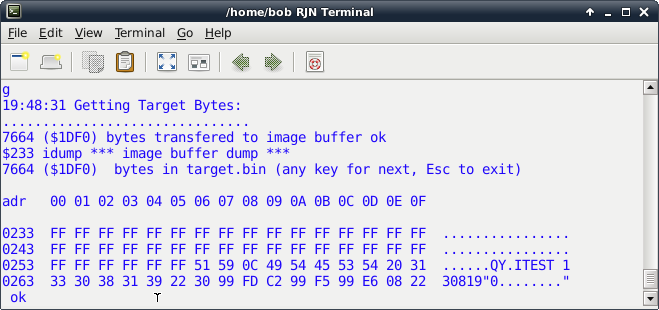
Photo 6 -- Target Image Dump
Use the "idump" command to view the Target image buffer. When executed without an input parameter, it displays starting at the first Target byte, offset 0 in the image buffer. When executed with an offset address on the stack, "idump" starts its dump at that address. As shown above, the dump displays the usual header information and provides an ASCII decode field for each line of 16. To continue a dump, press the space bar; to terminate a dump, press the escape key. The dump aborts for addresses greater than the size of the file.
Page 28
When the interactive programming session starts up, it reads the programming image, target.bin, into an image buffer. This buffer is used to program the Target and is compared against the Target image buffer by the "diff" command to verify correct programming.
To display the chip image buffer, use the "cdump" command. This command works in much the same way as the "idump" command.
The utility menu, shown by the "u" command, describes the usage of the dump commands and some less-used but similar utilities for examining the Target and chip image buffers.
The "diff" command compares the contents of the Target and chip buffers, byte by byte, producing a results display with the total number of buffer bytes, the total number of matches and the total number of errors. The results are displayed in both decimal and hexadecimal.
If there are mismatches, the "diff" command displays the address of the mismatch, in addition to the normal summary information. This sometimes produces a large screen full of addresses, especially if the Target image has not been loaded with the "g" or "f" commands. Of course, you can save the target image to target.img and use the Linux diff command to compare it to the target.bin file. You can do this at a Gforth command prompt by shelling out with the "sh" Word.
The "i" command reads the ID and revision information from the Target and displays it. Also displayed is the chip type, if it can be decoded. The programmer can decode all of the chip families given in Table 10 in the SL application note AN127 with exception of the few chips that have FPDAT addresses other than $b4 (0xB4).
The chip families not decoded are 'F34x, 'F38x, 'T62x (OTP) and 'T32x (OTP). Adding support for these chips is straightforward (see the C2.fs and commands.fs source code files). Although the C2 primitives defined in the C2 source code can be used to modify the rom in the One Time Programmable (OTP) chips, this has not been done.
Note that the "i" command is normally executed after it has been determined that a Target is present. In the "pc" script, this is done by the "?target" command. It is also done whenever an interactive session is started. The "?target" command can be executed from the Gforth command line but is not much use after an interactive session is in progress. If a Target is not detected, in either command or interactive mode, the program aborts with an error message (manual intervention is required).
The "v" command reads the program name (PROG or PROG-850) and revision number (coded date) from the IPP. This is displayed in both interactive and command modes. A typical revision number would be 130817 indicating an IPP compilation date of August 17th, 2013.
Page 29
The "e" command erases the Target chip. The "p" and "d" commands both erase the chip before programming. All flash bytes in an erased chip are $ff. The "p" command examines the next block to be programmed and, if it consists of all $ff bytes, does not send the block to the IPP. However, it does send data to the IPP to adjust its current programming address. On the 850 programmer, both the "p" and "d" commands check for blocks (or partial blocks) that do not need to be programmed.
The ".adr" command can be used to display the current value of this address, although this function is primarily of use when transmitting individual blocks (see the commands.fs source code file and the "u" menu).
The "rst" command sends a command to the IPP telling it to reset itself. The IPP does this by jumping to its cold start vector. This command is executed to ensure that the IPP is in a known state before starting a programming session.
The "tr" requests the IPP to reset the Target. This reset is performed with a C2 reset command (i.e., the Target's reset line is held low for approximately 40 microseconds to force a reset). When the Target is being programmed in-circuit, the "tr" command may be needed to force the Target to restart and perform normal initialization after programming. Note that powering down the IPP also resets the Target.
Page 30
The "clone" command is implemented as a command script. The inset below lists the contents of the clone script. Note that it resides in programmer application directory (e.g., the ~/myforth/projects/prog directory).
# clone -- clone a chip from target.img  -- 13Aug13 rjn
#
# resides only in the PROG directory
#
# ======================== CLONING A CHIP ===================================
#
# 1. Put the chip to be cloned in the Target socket.
# 2. Change to the prog directory (e.g., using the "prog" alias).
# 3. Bring up the programmer in the interactive mode with the "p" command
#    and execute either the "g" or "f" commands.  This copies the Target
#    image to the image buffer.  Execute the save-image command tos save the
#    buffer image to the target.img file in the prog directory.
# 4. Remove the chip to be cloned from the Target socket and insert a
#    new Target.
# 5. Execute this script to rename target.img to target.bin and program
#    the new Target with the cloned image.
# 6. You can repeat the cloning process by inserting another new Target chip
#    and executing "clone" again.
# 7. Note: Many chips now have the version number embedded at the start of rom
#    (e.g., $233 for the 300 chip).  See the job.fs file in the prog directory
#    to see how to do this.  If the revision string is present at the start of
#    rom, you can execute "$233 idump" after executing the "g" or "f" commands
#    to see a decoded dump of the revision string.
#    This is generally a good idea so that you can confirm the revision number
#    of the chip you are cloning.
#
# set -x
#
declare -x PROJ="/home/bob/myforth/projects"
cp ./target.img ${PROJ}/prog/chip.bin
./pc
echo " Target cloned from target.img"
The above command script provides the information needed to clone a chip. To clone a chip, first use the interactive mode ("p" command) to read the Target to be cloned with the "g" command. Save the Target image to the target.img file using the "save-image" command. Once the Target image is saved, exit the interactive mode (with "bye") and insert a new Target chip in the Target socket.
Executing the clone command (e.g., "./clone" from the programmer directory) programs the new chip with the copied Target. The "clone" command copies the target.img file to the programming file, chip.bin, and programs a new Target by calling the "pc" script. If you have the binary programming image of the Target to be cloned, copy it to chip.bin, executing "clone" as many times as needed to program the new Targets. After cloning, you may want to recompile the programmer source (e.g., using ./c or ./p) to ensure that chip.bin contains the latest version of the IPP.
Page 31
| pc (program chip) | Program the Target Chip |
| p (start new interactive session) | Command mode: start new interactive session. |
| p (interactive program command) | Interactive: Program the Target |
| d (download to Target) | Download (program) bytes to Target. This is a buffered transfer. No empty block check (slower than p). |
| f (fetch Target) | Fetch Target bytes (block size=$40), store in image buffer (ibuf). This is a buffered transfer. |
| g (get Target) | Get Target bytes (block size=$ff) and store in image buffer (ibuf). This is a direct transfer from the Target (unbuffered). |
| diff (compare Target & Chip buffers) | Verify programming by performing a byte-by-byte comparison of the Chip and Target image buffers. Displays total bytes, total matches and total errors, in hex and decimal. Error addresses are also displayed. |
| idump (dump Target image) | Dump Target image buffer. Starts at offset address $0000 if no address on the Gforth stack. Otherwise, starts at address on the Gforth stack. |
| cdump (dump Chip buffer) | Dump the Chip (programming) buffer. Starts at offset address $0000 if no address on the Gforth stack. Otherwise, starts at the address on the Gforth stack. |
| i (info) | Display IPP and Target information such as version, ID and revision. |
| v (version) | Display IPP programmer version. |
| e (erase) | Erase the Target chip. |
| rst (reset IPP) | Reset the interpose processor (IPP). |
Page 32
| Command | Description |
| tr ( Target reset) | Reset the Target chip. |
| clone (clone a chip) | Execute the "clone" command from a console prompt. The image of the chip to be cloned must be in the target.img file. |
Page 33
The development and execution environment for the programmer requires both Gforth and myforth.
First, download the myforth source for the 300 programmer (as a gzip tar file) and extract it to the myforth "projects" directory (e.g., ~/myforth/projects). Alternatively you can download the myforth source for the 850 programmer that uses the 850 Toolstick daughter card.
The download files extract leaving a folder named "prog" or "prog-850" with the programmer source code in it. Assuming that you have the normal myforth directory structure, put this folder in the "projects" folder. For example: ~/myforth/projects/prog or ~/myforth/projects/prog-850 . The latest myforth release is available at this site. Although the special function register (SFR) definitions for the 850 chip have not yet migrated to the main distribution, the SFR file, sfr85x.fs is included in the prog-850 directory.
For Debian distributions, install Gforth in the normal way with "apt-get update" followed by "sudo apt-get install gforth" at a console prompt. Gforth is normally installed in the /usr/local/bin or /usr/bin directories.
To confirm this, enter "which gforth" at a console prompt and then enter something like "ls -al /usr/bin/gforth" to get the name of the executable. For example, the version might be "gforth-0.7.0" for a Raspberry Pi. Change the references to Gforth in the "p", "pcx" and "c" command files to agree with the version you have.
The serial data link to the IPP is normally made with a USB to serial adapter or a hardwired connection.
Most newer PCs lack a dedicated serial port. It is relatively easy to install a USB to serial adapter on a PC without a hardwired serial connection. Normally you only need to plug in the adapter and the operating system will find it. In rare cases you need to reboot.
Assuming you have rebooted with the adapter plugged in, you find out how it was mapped to a device file by executing something like "dmesg | grep "ttyUSB*" at a console prompt. On my "big" system the two adapters that I have connected were mapped to ttyUSB0 and ttyUSB1.
Whatever the mapping, you must edit the ~/projects/prog/serial-linux.fs file to agree with the serial device you are using. In the file around line 41 you will see: here ," /dev/ttyUSB0". Replace the "ttyUSB0" with the device name you are using.
If you are using a processor with a hardwired serial port, the device name must also be changed to agree with the startup mapping. For the Raspberry Pi, the serial port is hardwired and mapped to "/dev/AMA0" -- there is a line that is commented out in the serial-linux.fs file to make it easier to change to the Pi.
Four different USB to serial adapters were tried with my (somewhat older) Linux PC. All have worked without problems. These adapters all use either the FTDI or CP2102 chips. The one I like best is the FTDI Friend from Adafruit but it costs around $15.
Page 34
We include a USB to serial adapter with one of our products. We buy these on EBay from Chinese suppliers for about $3 each. We have tried two different kinds and both work. We have also tried (and like) the FT-232R Breakout board from Sparkfun but it is a bit of overkill for this simple application.
No matter what USB adapter you use, be prepared for somewhat slower downloads. All of the adapters we have used seem to be slow in delivering bytes to the programmer. The receive speed is what you would normally expect.
The slow delivery may be related to on-chip buffering or to the USB drivers. We are confident that the problem is not with Gforth, although it does have its own serial "issues" (see below).
Examining the startup messages associated with some of the adapters we have noted a mention of a 64 byte buffer on some of them. Even with buffering, the serial rate should not be more than twice as slow, as we have observed it to be.
The cure for this is to use real serial ports but this is not always an option on newer PCs. We solved the problem by using the Raspberry Pi to run the programmer. We now routinely program applications by establishing a SSH link to the Pi and executing the programming commands from the "big" machine.
On the Pi, both programming and readout are as fast as one would expect for the baud rate. Thus, without skipping any blocks, a 'F300 chip can be programmed and verified in 10 to 12 seconds. With a USB to serial adapter and no block skipping, just programming a 'F300 can take around 35 seconds at 19.2K baud.
Here are the approximate times we recorded for various operations using Raspberry Pi:
For the sake of completeness, here are the typical times for a USB to serial adapter at 19.2K baud:
Page 35
As mentioned earlier, there is a problem with the Gforth Word to check for a serial character being ready. The problem is in the definition of key?-file. If a Word using this is used to check for a serial character being ready, it will hang. The normal serial input works, but it uses blocking I/O and will wait as long as needed for a character.
To avoid this problem, the PROG software was designed to only use blocking I/O. We have not had any major problems using this, but IPP Words were designed to always return a single character response (except for some Words such as "v" which expects a fixed number of bytes). This design allows the programmer to be built that is compatible with any verision of Gforth.
Fortunately, this problem has been fixed and the next release should work. Also, the fix can be applied to existing systems using the latest files in the git archive. Bill Kibler has done this for several PCs, including my "big" system and for his BeagleBone Black. The fix requires recompilation from source and a working Gforth (any revision). Although the serial problem does not affect the PROG programmer, users interested in the fix may contact the author for assistance.
Page 36
Initial Release |
||
Revised for 850 changes (e.g., big buffer, no "f" command, "d" block skipping). |