This application note describes how to load firmware updates into BOBZ products using the Silicon Laboratories, Inc. (Silicon Labs) Integrated Development Environment (IDE) and their USB Debug adapter.
For our products that support a firmware download, programming connections are brought out from our BOBI (Bob Interface) connector. This connector is included in all of our new programmable products. This interface provides power, ground, a serial port and a C2 programming interface.
We have also designed and imlemented a small breakout board for use with the BOBI interface so that programming connections can broken out for our standard 4-pin programming interface. This note shows how this adapter connects to the BOBI connector, how to connect the programming pins to the Debug Adapter and how to use the Silicon Labs IDE to perform a firmware update.
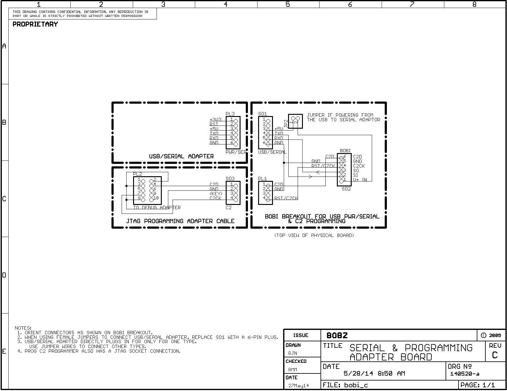
Schematic 1 shows how a product connects via a breakout board to a USB to serial adapter and to a programming adapter cable. The programming adapter cable is the focus of this note: it connects between the Silicon Labs Debug Adapter and the C2 programming pins on the breakout board.
The schematic consists of a group of three cartouches:
The BOBI Breakout Board connects directly to the BOBI interface of the device that needs a firmware update. The board breaks out the BOBI connections into two connectors. One connector connects to a USB to Serial Adapter that typically supplies 5 Volt power, ground and two serial lines to the product. Another connector wires to the programming adapter.
The connections between the adapters and between the product and the breakout board typically consists of socket to socket jumpers installed on stake pins.
The programming adapter can be implemented a number of ways but is shown as a custom cable in the schematic. The programming adapter converts between the 2X5 IDE socket on the end of the Debug Adapter's programming cable and the 4-pin programming interface on the breakout board.
Page 2
The programming adapter can be built as shown, with direct-wired connections between a 2X5 socket and a 1X4 IDE socket. The cable length should be under six inches.
Perhaps a better way to build the programming adapter is to mount a 2X5 shrouded IDE plug assembly on a small piece of perf board, performing socket and cable connections on the board. This makes it easier to wire and also makes it easier to plug in the Debug Adapter.
If using the proto board to mount the 2X5 plug, the C2 programming connection can be provided by a three-pin stake pin header. Socket to socket jumpers can then be connected directly from these stake pins to the BOBI interface. The jumpers should be under six inches.
If wiring to the breakout board's programming connector, note that one of the pins of the 4-pin C2 connector is unused: it is filled with the end of a toothpick to provide keying for the 3-wire C2 connection.
When the Debug Adapter and C2 interface are connected with the adapter cable, the Silicon Labs IDE should be able to connect to the chip on the board being updated, the Target board. To connect, select the "Debug/Connect" menu option on the IDE. When the chip is connected, the "Target:" label at the bottom of the Window shows the type of chip (e.g., "C8051F850").
Once the Target's chip is connected, use the "Debug/Download Object File" option on the IDE to bring up a download dialog. First, use this to erase the chip memory.
Next, download the firmware update file. Firmware updates consist of a chip program image in Intel HEX format. The programming dialog allows you to select this format. It also allows you to navigate to the location of the update file (perhaps your standard download directory).
It is beyond the scope of this note to describe how to use the IDE for other functions such as configuring the Debug Adapter. But, this is covered in various Silicon Labs documentation.
Firmware updates from Linux are a bit trickier. We program our boards with the PROG C2 Programmer. We can furnish programmers or you can roll your own with the instructions provided in the PROG manual. We have not tried to run the Silicon Labs IDE in Linux using Windows comatibility programs such as emulators or virtual machines.
Initial Release |
Copyright © June 1, 2014, Bob Nash.