The following describes MIDE, an interactive development system for myforth applications. MIDE stands for "MyForth IDE" and is a tongue in cheek reference to our minimalist version of an "IDE." The PROG C2 programmer project uses a specially-programmed 850 chip to download programs into chips.
The MIDE project extends the PROG programmer to implement a "one-wire" (half-duplex) tether allows you to go from programming to tethered debugging without switching any connections. The debug tether does not use any additional pin resources because it uses the same bi-directional C2 data line used for programming.
With the one-wire tether, all myforth definitions (other than macros) can be executed interactively. The one-wire tether is particularly useful for applications that use the serial port for purposes other than debugging.
The tether also allows interactive execution of words that do not need to be visible in a standalone interpreter's dictionary. For applications not using the serial port, debugging does not require compilation of the standalone interpreter and allocation of the serial port pins.
Page ii
(BLANK)
Page 1
Page 2
Page 3
As described on the title page, the Myforth Integrated Development Environment, MIDE, consists of the PROG C2 programmer with software extensions for a one-wire half-duplex serial tether to the Target chip.
Except for tethering extensions, the development environment is the same as that described for the PROG programmer. The development environment consists of four major elements:
Page 4
The Linux Host PC can use a USB to serial adapter to communicate with the IPP programmer/tether. This document also describes how a network link to a Raspberry Pi can be used to provide the tethered link via a hardware serial port for faster programming. The Linux Host and (if used) the Raspberry Pi require the installation of Gforth (as with the PROG C2 programmer).
The Interpose Processor (IPP) includes the programming firmware described in the PROG C2 programmer and also includes the tethering extensions. The additional code for tethering consumes approximately 700 bytes.
The IPP connects to the Host in the same way as described in the PROG documentation. For development with just the Host, the connection is typically a 19.2K serial data link provided by a USB to serial adapter. A network connection to a Raspberry Pi allows faster programming using the Pi's hardware serial port. The network connection also serves for the tethering communication.
The Target processor requires only chip power and a three-wire programming connection (two chip pins plus ground). Note that one of these pin connections is to the reset pin so that the Target application must reserve only one pin for the tether. With some care, the application's digital I/O can usually share the tethering connection.
Shell scripts simplify compilation, tethering and the transfer of application files to the Pi. Typically, programming files and source code can be transferred between the Host PC and the Raspberry Pi using a few shell scripts invoking SSH (secure shell) or SCP (secure copy).
There are only a few of these scripts and they are included in the software distribution and explained in this documentation. Most users will want to customize these scripts for their own development needs, but they can can be used "as is" if the development directory structure is the same as that typically used for myforth development.
We recommend that you go to the Downloads section and download the MIDE source code so that it is readily available for reference in the following descriptions. Also available in the Downloads is an early version of the dacs application mentioned in several later sections.
Page 5
There is little to say about design considerations, except for the one-wire tethering. Most of these "considerations" are more like "constraints", as the goal was to use the IPP and its existing connections for the one-wire tether.
The one-wire tether is implemented as a half-duplex bit-banged serial link using the C2 data pin (C2D).
The operation of the link is described in more detail in later sections. The link operates at 19.2K baud. This rate was arbitrarily selected to match the serial rate of the IPP, but could be easily changed to support higher rates (or even non-standard rates). There is no need to match the IPP data link with the tethering link: exchanges on the tethering link are transparent to the Host.
Although not an initial design constraint, the implementation did allow the tether to operate in the same way as the normal myforth serial tether. The tether provides the following features:
The one-wire tether also allows the Target to be tested with the Tether while also running a standalone interpreter (which can also be useful during testing).
When both tethered and standalone links are used, a second serial link for the standalone interpreter is typically implemented with a USB to serial adapter and minicom connected to the Target. This kind of operation is described more fully in later sections.
Page 6
The tether requires facilities on the Host, the IPP and the Target.
The Host runs the normal myforth tethering software. Only trivial changes were made to the myforth compiler software in the misc8051.fs source file. One change is the addition of a word, "posing", which simplifies the switching between tethered operation and Host (interposing) operations.
When in the interposing mode, the Host is in direct communication with the IPP's interpreter and can examine the IPP stack, etc. Additional words are defined elsewhere to aid in switching between tethered and normal operation.
During tethered operation, the IPP runs a special tethering word that primarily translates full-duplex serial data from the host to the half-duplex bit-banged serial data exchanged between the IPP and the Target.
The IPP tethering word performs the following:
The operation of the IPP tethering word is described in more detail in following sections.
The Target tethering word is a continuous loop that performs the following:
The operation of the Target tethering code is described more fully below.
Page 7
As mentioned above, only a few changes were needed in the normal tethering software so that it could also support one-wire tethering. This section describes these changes and provides a review of the existing tethering code.
Figure 1 shows the essential elements of the tethering code contained in the misc8051.fs source file.
  \
  variable talks 0 talks !
  : talking  true talks ! ;

  : posing  0 talks !  $ff emit-s  key-s drop ;  \ -- 10Sep13 rjn
  \
  : listen  begin  key-s dup 7 - while  emit  repeat  drop ;

  : (talk)  ( a - ) ( clean) 0 emit-s key-s
     drop dup $ff and emit-s 8 rshift $ff and emit-s ;

  \ Enabling the '[char] | emit' marks results coming from target.
  \ Words executed only for the host won't do that.  A debugging aid.
  : talk  ( a - ) >red ( [char] | emit) (talk) listen >black ;

  :m call  ( a - )
    	hint
   	[ dup $f800 and ] here [ 2 + $f800 and = if
		  dup 8 rshift 32 * $11 + ] , , [ exit
	   then $12 ] , [ dup 8 rshift ] , , m;

  :m -:  (  - )
   	[ >in @ label >in !
   	create ] here [ , hide
   	does> @ talks @ if  talk exit  then ] call m;

  :m :  (  - ) -: header m;
  \
Figure 1. Host Tethering Words
Starting from bottom to top in the code above, the "colon" macro is the basis for myforth definitions. It simply invokes "-:" and compiles a header. The "-:" word is used for myforth words that do not require a header. For applications not using the standalone interpreter, the headers are not compiled on the Target.
In "-:", examine the code phrase starting with "does>", which defines the behavior of the word being defined when it executes. It first fetches the code field address, as is normal. Next it uses the "talks" variable to switch the definition's execution behavior depending on the talk value.
Note that the "talking" and "posing" definitions manipulate "talks" to control the behavior of all defined words.
Page 8
When "talking" (talk is true), definitions execute "talk" and then exit without calling the word. This is the behavior of interest. The talk word uses the execution address, fetched by the "@" after "does>". Talk first executes >red (defined elsewhere) to change the text color to red. This emphasizes that the responses shown on the screen come from the Target. Optional code also puts a "|" marker to further emphasize this.
The ">black" word at the end of the definition restores the normal cursor.
Talk first calls "(talk)" that first sends a null to the serial port. With normal tethering, the Target responds to this. In the one-wire case, the IPP responds. The IPP echos the byte back to "(talk)" to indicate it is listening. The "(talk)" gets this response using key-s and discards it with a drop. So far, not much exciting has happened.
Remember the execution address that was hanging around on the stack? It is now used to separately extract the upper and lower bytes of the execution vector for transmission to the Target. The two bytes are extracted by masking and right shifting, per conventional coding.
Assuming that the IPP is on the other end, these bytes are translated to their bit-banged serial versions and sent to the Target for execution. IPP coding and Target behavior are described more fully in following sections.
Now that we are done telling the Target what code to execute, we must prepare for a response. Response handling is performed by the "listen" word.
Bytes coming back from the Target (via the IPP) are collected with a "begin .. while .. repeat" loop that terminates upon receipt of a byte value of 7. This is a special value used to indicate the end of a response. For many Target words there is no response other than the 7, which can be viewed as an "ok" response from the Target (via the IPP).
It may appear that including 7 in a response string is a problem. It is, but not much of one: typically, responses are ASCII characters and 7 does not normally appear in the return data. Note that "listen" uses "emit" in the loop to show ASCII characters. A typical byte string from the Target includes ASCII data returned by words for a stack or memory dump (see Photo 7).
This completes a Host to IPP transaction.
In summary, the user selects tethering with "talking" and then enters the selected Target word on the Gforth command line. The Target word's behavior is modified in the tethered mode to send the Target's execution address to the serial port for eventual receipt and execution on the Target. After the Target completes its execution, it returns and ASCII response (if any), followed by a 7 byte to indicate completion.
Page 9
Before leaving the discussion of the Host words, consider the code in Figure 2.
  \
     [ : targeting  postpone [ iq target talking ; immediate ]
     [ : posing    0 talks !  $ff emit-s  key-s drop  postpone [ ; immediate ]
  \
Figure 2. Tether Control Words
The two words shown above, "targeting" and "posing" make it easier to switch between tethering and interaction, via the Host, with the IPP.
The "targeting" word activates the tethering code on the IPP by executing "iq" (IPP quit). This is discussed more fully in a following section.
The "target talking" phrase switches to the Target vocabulary and executes "talking" to change the execution behavior of Target words for a tethered connection, as described above. The brackets, "postpone" and "immediate" ensure that the correct vocabulary is selected when certain words are executed and to ensure that "postponed" words are executed rather than compiled.
The "posing" word terminates tethering behavior on the Host (with "0 talks !") and also terminates the tethering loop on the IPP, iq, with with the transmission of a $ff byte. This is described in more detail in a following section.
Because the normal behavior of the IPP tethering loop is to echo back characters, the response is received (with key-s) and discarded (with a drop).
Thus, "targeting" starts up the IPP tethering loop and changes the execution behavior of Target words to the tethering mode. In a complementary fashion, "posing" backs out of the tethering mode by restoring the behavior of Target words to compiling and shuts down the IPP tethering loop with a transmission of a $ff byte.
Page 10
The coding of the bit-banged serial interface is straightforward and is based on four serial I/O words: ie, ik, te and tk . These correspond to interposer emit (ie), interposer key (ik), Target emit (te) and Target key (tk).
Additional (optional) code is provided to allow for timeout of the target key word so that the IPP will provide a response regardless of the responsiveness of the Target.
As one might expect, the routines are quite similar, differing primarily in the port pins used and the data direction.
As noted earlier, the bit-banged routines presently operate only at a rate of 19.2K baud. Hopefully the details that follow will allow users to change this, if needed. Note that there is no particular advantage to increasing the data transfer rate, as most interaction takes place at the speed of human fingers.
The tethering words are currently incorporated in a single file, mide-tether.fs. The following examples are taken from this file.
Page 11
  \
  0 [if] \ ------------------[ precise timing ]----------------------------------
  \
  \ assumes 24.5 MHz internal clock
  \ gives the precise timings for 19.2K, 52 usec/bit (4 bits=208us)
  :m 488ns  1 # delay6 nop nop m;
  :m sd/2  29 # |us  488ns 488ns m;  \ uses registers 6, 7
  :m s-delay  sd/2 sd/2 m;
  :m b-delay  8 # 5 #for s-delay 5 #next m;  \ byte delay
  \
  [then] \ ----------------------------------------------------------------------
  \
  1 [if] \ ----------------[ good enough timing ]--------------------------------
  \
  \ assumes 24.5 MHz internal clock
  :m 408ns  1 # delay6 ( nop nop) m;  \ calculated, not measured
  \ making sd/2 callable vs. a macro adds ~ 320 ns per call (8x40 ns)
  : sd/2  29 # |us  408ns 408ns ;  \ uses registers 6, 7
  \ making s-delay an ajump vs. a macro adds 320 ns
  : s-delay  sd/2 sd/2 ;
  : b-delay  8 # 5 #for s-delay 5 #next ;  \ byte delay (lots of latitude here)
  \
  [then] \ ----------------------------------------------------------------------
Figure 3. Bit Timing Words
The first code to be examined is the bit timing code shown in Figure 3 above.
Two different timing options are provided, precise timing and "good enough" timing. Precise timing is implemented as macros to avoid having to calculate timing based on multiple calls and returns. The "good enough" timing is reasonably precise (within a microsecond) and is used to reduce the amount of code required for the tether.
Note that, with the Silicon Laboratories 8051 implementation, a call takes three cycles and a return takes 5 cycles (!). Thus, the routines were adjusted by 8 cycles or approximately 320 nanoseconds.
The "good enough" timing was adjusted somewhat for the calls and returns but was not verified on an oscilloscope, as were the precise timing words. However, the "good enough" words were tested with a minicom terminal (as were the precise words).
The fundamental delay word is sd/2 which provides a delay of approximately half a bit time (26 microseconds). The s-delay word provides a full bit delay by invoking sd/2 twice.
A third word, b-delay, provides a delay approximately equal to one byte. This was needed in some words to allow for processing to complete on the previous byte. This delay is approximate and was tuned to provide reliable operation for multiple byte exchanges with the IPP.
Page 12
Figure 4 below shows the implementation of the bit-banged serial output word for the IPP, ie (IPP emit). The corresponding word for the Target, te (target emit), is similar but uses the Target's c2d pin, tc2d, for output. The te word is not discussed here but can be examined in the mide-tether.fs source file.
The pin usage for the IPP and the Target can be confusing. Recall that the C2 programmer uses port 0, pin 1 (P0.1) to exchange programming data with the Target. In the code, this pin is designated "c2d" although it is not actually the c2d pin of the programmer. The Target exchanges programming data using its actual c2d pin (P2.1). In the tethering code, this pin is designated "tc2d" to emphasize that it is the Target's actual c2d pin.
  \
  \ -----[ ipp bit banged serial I/O ]
  \
  :m (iemit)  ( n -)  \ send lsb first
     8 # 5 #for
        [ rrc c2d movcb ]  \ send lsb from T to c2d
        s-delay
     5 #next  drop m;
  \
  : ie  ( n --)  \ bit-banged serial emit
     c2d-out  [ c2d set ]  b-delay  ( allow target to complete)
              [ c2d clr ]  s-delay  ( start bit)
     (iemit)  [ c2d set ]  s-delay  ( stop bit) ;
  \
Figure 4. Bit-Banged IPP Output
The IPP emit word, ie, assumes that the byte to be transmitted is on the Interposer's stack. The IPP's c2d driver pin is connected to the Target. It is first set to an output with c2d-out and set high with the "[ c2d set ]" assembler sequence. This is followed by a byte delay (b-delay).
At this point, the IPP output has been set high for approximately one byte time. This delay of approximately one byte ensures that the Target has finished processing any previously-sent byte. This delay is longer than strictly needed but was set at a full byte so that the timing would be conservatively long.
The following line in the ie word implements a start bit, pulling the data line low for a full bit delay.
The next line starts with (iemit) -- it outputs the data bits. It is a macro that sends the byte on the IPP's stack, lsb first, to the Target. The eight bits of the byte are sent in a for ... next loop implemented with register 5. Within the loop, the phrase "[ rrc c2d movcb ]" rotates the lsb right into the carry bit (rrc) and then moves the carry bit into the c2d output pin (c2d movcb). This bit operation is followed by a full bit delay before the loop processes the next bit. The drop at the end of the (iemit) routine drops the byte on the IPP stack.
The final code in the ie word sets the c2d pin high and delays for one bit. This implements the stop bit.
Page 13
  \
  [ \ Gforth
  : tq   [char] t emit-s  [char] q emit-s  isend ;  \ Target quit (execute on Target)
  : iq   [char] i emit-s  [char] q emit-s  isend ;
  ] \ myforth
  \
  \ -----[ target quit ]
  \
  : tok  7 #  te ;
  -: tex   push push ;  \ target execute
  \
  : tq  tk tk tex tok tq ;
  \
  : tnumber 5 # te  tk ;
  \
  \ -----[ interposer quit ]
  \
  \ :m iok 7 # (emit) m;
  \
  \ target response processing --
  \
  \ 7 -- normal action: pass to Host
  \ 5 -- waiting for byte (e.g., tnumber)
  \
  : ?response  ik
      7 # xor 0=if drop iok                   ; then 7 # xor
      5 # xor 0=if drop iok key ie ( ik drop) ; then 5 # xor
      emit ?response ;
  \
  : iq  key dup (emit) if drop ; then drop  key key ie ie ?response iq ;
  \
Figure 5. IPP and Target Tethering Code
The code for the IPP Tethering interface is shown in Figure 5 above.
Starting from the bottom of the code shown above, consider the coding of "iq" (IPP quit), the loop that implements the IPP tethering code. The first action of "iq" is to receive a byte from the Host (key) save a copy and echo it back to the Host.
During tethered operation, a null byte is transmitted from the Host to initiate a tethering transaction. However, an $ff byte can also be sent from "posing" to terminate the IPP tethering loop. Observe that, if a non-zero value is transmitted to "iq", it drops the value from its stack and exits the tethering loop (i.e., with the "if drop ;" phrase).
Under normal tethering conditions, "iq" executes the phrase "key key ie ie ?response iq." This gets the two execution vector bytes from the Host (with "key key") and sends them to the Target using bit-banged serial output on the IPP/Target link. The operation of "ie" is explained in the previous section.
Page 14
The most complicated part of the IPP tethering loop is the action of the "?response" word. It starts by receiving a response from the Target with the bit-banged serial version of "key" for the IPP, ik (interposer key). Once it receives a byte from the Target, the byte is processed according to its value.
The easiest case to understand is a Target return of 7. The phrase "7 # xor" performs an exclusive or on the response and, if the result is zero (a match), the returned response is dropped and the IPP echos a value of 7 back to the Host (with "iok") and exits. This is the normal action for a Target word that executes and returns an "ok" response of 7. If the returned value is not a 7, then the phrase "7 # xor" (after "; then") restores the original value so that it can be processed by following code.
The next case is a Target return of 5. This is a new "special case" number added for the one-wire tether. If the Target responds with this value, then the Target word, during execution, has sent a response back to the IPP to indicate that it expects another byte.
Thus, a return of 5 can be viewed as a "key" request from the Target. The most common instance of this is when either "#" or "##" is executed to send a single or double number to the Target to be put on its stack. This is needed for words being tested that expect a value (or two) on the stack.
When "?response" processes a return value of 5, it fakes an "ok" response back to the Host so that it thinks the Target has responded with an "ok." After spoofing the Host, the 5-responder waits for a byte from the Host (with key). After receiving the byte from the Host, it sends it to the Target with "ie" (the interposer's bit-banged emit). After 5-responder finishes processing a 5, it exits "?response" (with ;), just as the 7-responder did. The phrase "ik drop" is commented out but left in the source code to note that the Target responds to the "ie" transmission but is ignored. The Target response is an artifact of normal Target tethering behavior and is not needed for elicited keys.
In the event that the returned byte is simply one of a sequence of ASCII bytes, "?response" processing defaults to sending the byte back to the Host (with "emit"). After echoing the byte received from the Target back to the Host, the default processing recursively jumps back to the start of "?response" to receive the next character. The "?response" loop repeats until a terminating value of 7 is received from the Target (the Target "ok").
The interposer's quit, "iq", is also recursive, processing input from the Host and translating it for the Target until it receives a termination value from the Host (i.e., as a result of "posing").
Note that there is also a version of "iq" defined in Gforth (the code within the brackets). This is necessary so that Gforth can send a sequence of characters to the IPP interpreter to start up the IPP tethering interpreter.
Thus, the IPP is normally waiting for commands from the Host and interpreting them. These commands would typically be programming commands that the IPP understands, such as "p" for programming. When the IPP receives the "iq" command, it enters the tethering loop until it receives an $ff flag from "posing" to terminate its tethering behavior.
Page 15
For an explanation of the Target tethering code, also refer to Figure 5.
The Target tether is defined in "tq" (Target quit). Besides being very alliterative, the definition is quite manic: it repeatedly receives two bytes from the IPP and processes them. These bytes are always assumed to be an execution address. The specified address is "called" by pushing the bytes on the Target's return stack (with "push push") and executing a return (with ";").
Once "tex" (target execute) has executed the bytes sent from the Host, it returns to execute "tok" (Target "ok"). This response is simply a 7 transmitted back to the IPP over the tethering link (with "te", target emit). Once the Target has responded with an "ok", it recursively returns to the start of the "tq" tethering loop.
After bootup and initialization, the Target continuously executes "tq" as part of the "go" turnkey word.
Refer to Figure 6 below for definitions to be placed in main.fs to support tethered or standalone execution of Target words. It is possible to terminate tethered operation with a hardware switch, entering the standalone interpreter upon tethered termination.
  \
  \ put these definitions in main.fs ( /chip initializes the chip)
  \
  -: go   /chip tq      \ for tethered operation
  \ -: go  /chip  quit  \ for standalone operation
  \
  \ Load an turnkey options for the job.fs file:
  \
  true    constant tethered    \ true only if tethering routines are to be loaded
  true    constant turnkeyed
  true    constant standalone  \ true if there is a standalone interpreter
  \
  \
  \ -----[ Choose interpreter(s) ]
  \
  tethered   [if] include mide-tether.fs      [then]
  standalone [if] include mide-standalone.fs  [then]
  \
Figure 6. Target Definitions for Tethered and Standalone Operation.
As shown above, for tethered operation, the turnkey word, "go" is defined to initialize the chip and enter the non-terminating "tq" loop. Because tq does not terminate, there is no need for a ";" at the end of the definition.
Just below the tethered definition for "go", is the definition of "go" for a standalone Target. This turnkey definition initializes the chip and enters the non-terminating standalone interpreter (with "quit").
Page 16
Also shown in Figure 6 are the options to be set in the job.fs (myforth job control file) to establish either tehered or standalone operation. Below these options is typical code for the job file that conditionally compiles the tethering or standalone interpreter code.
It is possible, even somewhat common, to have both tethered and standalone interpreters compiled during development. As previously noted, hardware switches can be set up to exit the tethering loop and enter the standalone loop. For production, the tethering code is typically not compiled ("tethered" is false).
One minor note: the inclusion of mide-standalone.fs is intended to load the version of the standalone interpreter used for programming. This version has been specially modified. Normally, the standalone interpreter will be modified to suit the application and the name of the standalone interpreter to be loaded will change accordingly.
Page 17
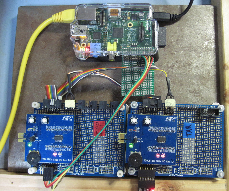
As shown in lower section of Photo 1, below, the typical MIDE development environment consists of an Interpose Processor (labeled "IPP") and a Target board that is under development (labeled "TAR"). For this discussion, both boards are 850 Toolsticks mounted on a proto board for power, serial and C2 programming connections.
The photo shows the IPP and Target board cross-connected with each board connected to the other with a programming cable. This is the development configuration used during development of the PROG programmer. Normally, only the programming connection between the IPP and the Target is required. It serves to program the Target and also provides the tethering link.
Photo 1 -- MIDE Development Configuration with Raspberry Pi
Page 18
At the top of Photo 1 is a Raspberry Pi with a serial port connection to the IPP (the multi-colored flat cable). These connections bring power (+5 Volts and ground) and serial I/O to the IPP. A network connection (yellow CAT 6 cable) provides an SSH connection between the Host and the Pi. This connection is also used to transfer files between the Host and the Pi.
The small perf board coming from the Pi's I/O connector is used to provide exposed stake pin connections while the Pi's cover is in place (the remaining part is unused).
For development without the Pi, the IPP would typically be connected to the Host with a USB to serial adapter.
Note that Target is shown with this kind of connection to the Host (lower left corner of the TAR board). This is because the Target application uses the myforth standalone interpreter. This connection tests the application and is also useful for debug. For example, words tested with the tether can output results to the Target's serial output. This is especially convenient when testing Target string formatting.
The development configuration varies depending on whether a Pi is used to communicate with the IPP to provide programming and tethering services.
Pi Development -- When the Pi's serial port is used to talk to the IPP, it is convenient to have a second terminal session for the SSH and SCP connections to the Pi. Thus, there are two terminal sessions: one for the IPP and one for the application itself.
Host Development -- When a serial port from the Host PC is used to talk to the IPP, only one terminal session is needed: the normal session with the application under development. Programming is performed by executing the "pc" script, as described in the documentation for the PROG C2 programmer.
The following sections describe Pi development and "Host only" development separately, although the procedures are quite similar. The Pi development is described first because it is somewhat more involved and because it is the method we use and prefer.
In the following sections, the application session may be called the "app" session (or just app). This is just a generic name for the application development directory. For example, when developing an application named "dacs", the app session would run from the "dacs" directory.
Several examples show the dacs directory to illustrate actual usage. The dacs application uses a C8051F850 chip to implement a simple data acquisition system using commands issued with a serial port (e.g., the Pi's serial port for Pi I/O).
In summary, the following sections describe how the configuration shown in Photo 1 in conjunction with one or two terminal sessions are used to develop a typical application. Differences between development with and without a network-connected Pi are small but are treated in separate sections so that you can select the method you prefer.
Page 19
Although development with the Raspberry Pi is very straightforward, there are a number of concepts and scripts to explain in this section. This may make Pi-based development seem more involved than it really is. To help understand the basics, here are the elements of Pi development:
In summary, editing test compilation is performed on the Host. Once there is a clean compile, the source code is transferred to the Pi for programming and tethered testing from the pt directory. A few scripts support this compilation, programming and test process. Although the details of these support script are explained in detail, their usage is straightforward.
Page 20
As noted above, Pi development requires two terminal sessions. One session manages network communication between the Host and the Pi. The other session displays the results of the Pi's serial communication with the IPP (e.g., during tethered testing).
The IPP session is executed from the "pt" (program and test) directory on the Pi. Typically, the directory would be: /home/pi/myforth/projects/pt .
It is convenient to establish a separate terminal session to manage network communication between the Host and the Pi. This session can be viewed as a window on the "pt" directory on the Pi. Thus, this network SSH session is called the "pt" session.
For the SSH session and for the file transfer scripts, it is best to set up key-based authentication between the Host and the Pi. This avoids having to frequently enter passwords. This process is described in detail at many sites, including the tecmint site.
The pit script establishes the pt session. This script normally resides in the mide (programming) directory on the Host. For example: /home/bob/myforth/projects/mide .
This location is mostly for convenience in bringing up the Pi session: the mide directory always exists (if you are using the C2 programmer) and it typically has an alias defined to switch to it. For example: alias mide='cd /home/bob/myforth/projects/mide' .
Figure 7 shows the pit script used to bring up an SSH session on the Pi (change the IP address to suit your configuration). Once connected, change to the pt directory. For example: alias pt='cd /home/pi/myforth/projects/pt' . Photo 2 shows a typical SSH session startup resulting from execution of the pit script.
   #!/bin/bash
   # pit.sh -- establish a pi ssh terminal -- 21Sep13 rjn
   set -x
   ssh pi@192.168.0.104
Figure 7. The pit.sh SSH Session Script for the Pi
Page 21
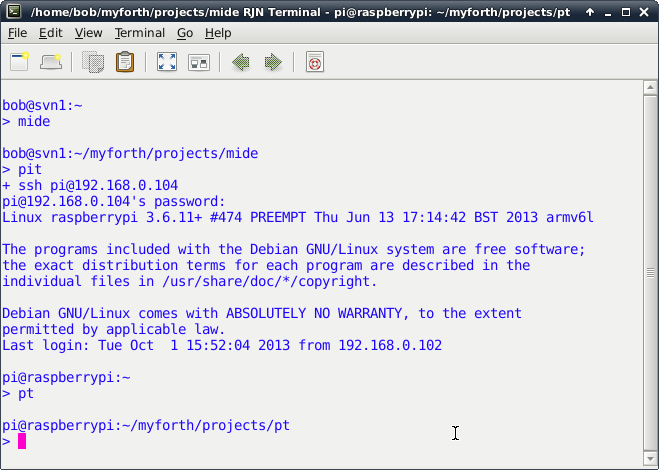
Photo 2. Startup Screen for Pi SSH Session
Setup of the Host session is relatively straightforward: establish a terminal session and change to the app directory (e.g., the "dacs" directory).
To easily change to the application development directory, we suggest establishing an alias in the .bash_aliases file. For example: alias dacs='cd /home/bob/myforth/projects/dacs' .
Page 22
The c.sh script compiles the myforth job file (job.fs). The job file loads the application source. It normally resides in the Host's app directory and, during development, it is used to verify that the application compiles correctly.
Like most other heavily-used scripts, it is typically defined as an alias in the .bash_aliases file in the home directory. For example: alias c='./c.sh' . This allows the application to be compiled by entering "c" in the application directory instead of having to specify the local directory with "./c.sh" .
Figure 8 shows the c.sh script contained in the Host's app directory. It invokes Gforth with a number of command line execution commands and also specifies several source code files to compile, as follows:
   #!/bin/bash
   #
   # c.sh -- compile job.fs -- 02Sep13 rjn
   #
   # set -x
   /usr/local/bin/gforth-0.7.9-20121007 \
           -e "fpath path+ ./ " \
           -e " 1 value com? " \
           -e " 19200 value current-baudrate " \
           ./serial-linux.fs \
           -e " open-comm"  ./job.fs \
   #       -e " bye"
Figure 8. The c.sh (compile) Script on the Host
The use of the c.sh script in the programming and tethering process is explained in more detail later. For now, it is only necessary to understand that, when executed from the Host's application directory, it compiles your application and establishes a serial port connection to the Target.
Page 23
If the application does not require a serial port (e.g., there is no standalone interpreter), the serial port statements given in the c.sh script are not strictly necessary. However, they do no harm and are typically retained regardless of the type of application under development. The serial port is closed when the GForth terminates with "bye."
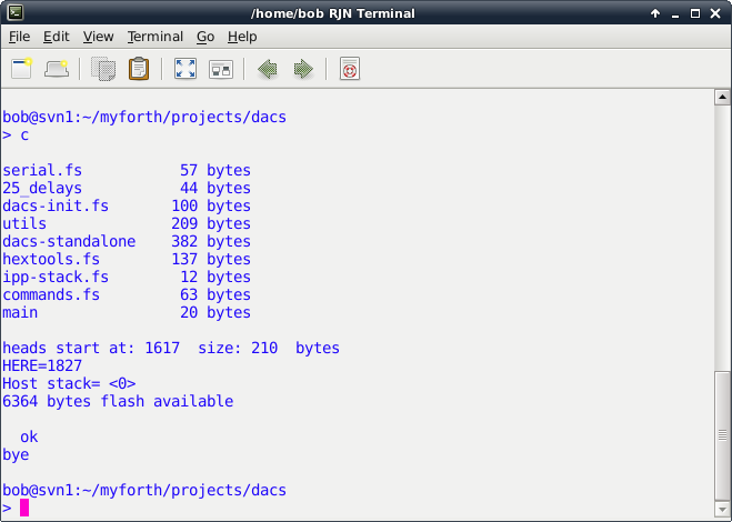
Photo 3. Compilation of the dacs Application with the c.sh Script
To program with the Pi's serial port, the chip.bin binary image produced by c.sh must be transfered to the Pi. This allows the Pi's serial port to be used to program the Target.
For tethering with the Pi, the application must be compiled on the Pi -- this is because the Pi's serial port must communicate with the IPP and have all of the application's definitions available for transmission to the Target.
Establishing the pt (program and test) directory on the Pi allows programming and tethering operations to be performed from a single directory. If a c.sh script is included in the pt directory, the application can be both compiled and programmed from the pt directory. Of course, the version of the c.sh script on the Pi must be changed for the Pi's version of GForth and its serial port.
Page 24
   #!/bin/bash
   #
   # c.sh -- compile job file (job.fs) -- 21Sep13 rjn
   #
   # set -x
   /usr/bin/gforth-0.7.0 \
           -e "fpath path+ ./ " \
           -e " 3 value com? " \
           -e " 19200 value current-baudrate " \
           ./serial-linux.fs \
           -e " open-comm"  ./job.fs \
   #        -e " bye"
Figure 9. The Pi Version of the c.sh Script
Figure 9, above, shows the version of the c.sh script that runs on the Pi.
To perform tethering, the pt directory needs to have all of the application source code. Because the Host generally has a superior programming environment, the source code is typically edited and compiled on the Host. After the compilation on the Host is good, the source can be transfered to the Pi for programming and testing.
The c.sh script on the Host can be used to compile the application. When there is a clean compile on the Host, the application source can be transferred to the pt directory on the Pi for programming and test. For programming, there is no need to compile on the Pi. But, source must be compiled on the Pi for tethering.
The topi.sh script in the app directory transfers the source code to the Pi. Figure 10, below, shows the contents of the topi.sh script that transfers files to the pt directory.
The script is a straightforward invocation of the "scp" (secure copy) command with the "-p" option to preserve the date and time stamps of the files. Photo 4 shows the result of executing the topi.sh script from the Host's application directory (in this case, "dacs"). Note that all source files are transfered along with the chip.bin file produced when the application was compiled (for programming on the Pi).
   #!/bin/bash
   # topi.sh -- xfr app. files to pt directory on pi -- 24Oct13 rjn
   #
   set -x
   scp -p ./chip.bin ./*.fs pi@192.168.0.104:/home/pi/myforth/projects/pt
Figure 10. The "topi.sh" Script
Page 25
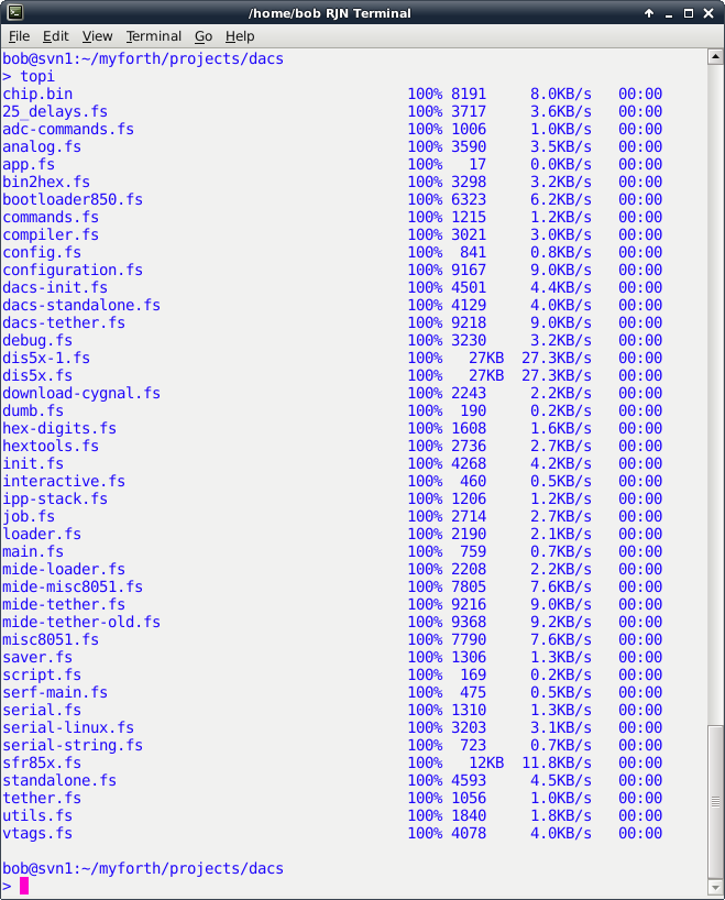
Photo 4. The topi.sh Script Transfering Files to the Pi
Page 26
The normal development procedure is to edit source on the Host, followed by a test compilation. With a good compile, the Host files can be transfered to the Pi. To verify the Host compilation, the source can be compiled a second time on the Pi to verify that the compilation results match those of the Host. The verification compile is performed with the c.sh script on the Pi. This script, of course, is customized for the Pi's environment (e.g., Gforth version and serial port parameters).
Note that a verification compile on the Pi is not required. But, if performed, the compilation should match that of the Host, as shown in Photo 3 (Host) and Photo 5 (Pi).
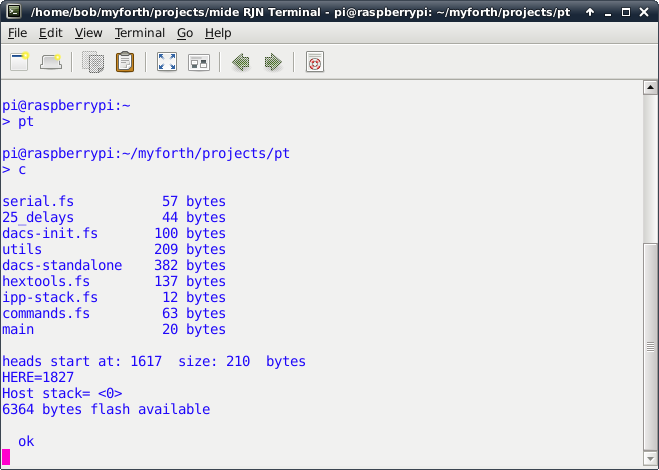
Photo 5. Application Compilation on the Pi
If the Host and Pi compilations do not match, it is likely because the topi.sh script did not transfer all of the files from the Host's application directory. To see which file may not have been transfered, look for mismatches in the total number of bytes compiled for each file.
Note that the compilation bytes primarily pertain to application files, not system files. System files, such as dis5x.fs (the "see" disassembler) and compiler.fs, are primarily Gforth files and typically have no application (Target) content. Because the topi.sh script copies all source files, it is unlikely that a source file will not be transferred. All source files should have a "fs" extension.
Page 27
The topi.sh script does not transfer any shell scripts from the Host. This is because scripts with the same name may not be the same on the Host and the Pi. Note that the scripts normally have "sh" extensions, per normal convention. Some of the examples show scripts executed without an extension. This is because they are aliased in the .bash_aliases file. For example: topi="./topi.sh" .
Page 28
As noted before, Pi development, with its two terminal sessions and support scripts, may appear to be more complicated than it is. Here is a step by step description of a typical development session on the Pi:
Page 29
Photo 6, below, shows a typical test session initiated from the Pi's pt directory. The Target has just been programmed with the dacs application and is executing "target quit" as its turnkeyed startup word:
-: go /chip tq
The application is compiled with the c script and was verified to be identical with the compilation in the Host's application directory. After display of the compilation results, the word "targeting" is entered to establish one-wire tethering with the IPP processor. At this point, Target words can be executed by simply entering them.
In this case, the word to be tested is "t11" which simply toggles the Target's Port 1, Pin 1. The Target is a Toolstick 850 board with an LED connected to Port 1, Pin 1. Thus, the LED will alternately turn on and off each time "t11" is executed.
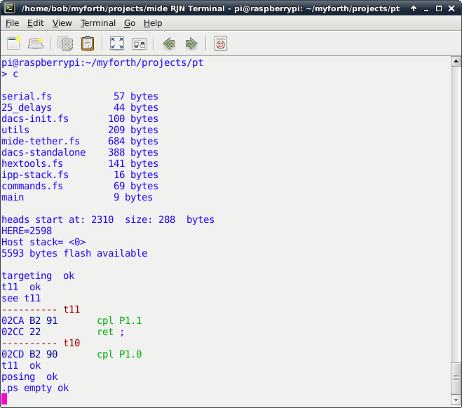
Photo 6. Application Testing on the Pi
Page 30
Following the execution of "t11", the "see" decompiler is used to display the source code for its definition (complement Pin 1 on Port 1 and return). Not shown is the exit from the "see" decompiler with the escape key. After exit, the t11 word is again executed to illustrate the seamless transition between viewing and executing definitions.
The word "posing" is executed next to exit the tethered mode, thus allowing the user to interact directly with the interpose processor. To illustrate this, the word ".ps" is executed to display the IPP's stack (it is empty).
Because the Target was turnkeyed with the tethered interpreter, it is always ready to talk to the IPP. For example, the user could enter "targeting" again and re-establish the tethering link.
A tethering session can be re-established after exiting the session (i.e., with bye). To do this, simply enter c to recompile the application and then enter "tethering" to establish a tethered link to the Target.
Some test words may instruct the Target to "jump to the weeds and die." To restablish the Target, simply cycle power or press the reset switch. Another approach is to bring up an IPP link with "c" and enter "tr" to reset the Target over the C2 link. The "tr" command works only when the session is first brought up or in the "posing" mode -- it sends characters to the IPP for execution by its standalone interpreter.
Caveat: do not enter "posing" when not already in the "tethering" mode. This will cause Gforth to hang (to recover: press Ctl-C followed by "bye" and bring the session back up with "c"). This hangup occurs because "posing" sends a character to the IPP quit loop and expects a character to be echoed back. Executing "posing" while the IPP tethered interpreter is not running will cause Gforth to wait forever for the return of a character from the interpreter.
Page 31
Development on the Host is simpler than Host/Pi development. There is no need for an SSH session to the Pi and all development is done from one terminal session in the application directory. The application is edited an compiled as normal, using the Gvim editor to navigate between source files and definitions from the job.fs file (e.g., using the j.sh script).
Once the edited application compiles cleanly (using the c.sh script), program the chip (somewhat slowly) with the "pc" (program chip) command, per normal procedure. The programming is performed from the mide directory, as described in the documentation for the PROG C2 programmer.
Tethered testing from the Host is the same as that described for tethered testing from the pt directory on the Pi. Simply enter "tethering" after compiling the application and test the Target words. Exit the tethering mode with "posing" or exit to linux with the "bye" command.
Photo 7 shows a tethered testing session performed from the dacs directory. The c script compiles the application and executing "targeting" enstablishes the tethering link with the IPP. The ".ts" command is executed to verify that the Target is responding. Note that the response is color-highlighted.
Next, "t11" is executed to toggle the state of the LED attached to Port 1, Pin 1. Following that, the "see" command examines the decompiled source for the t11 word. After escaping from the decompilation display (with Esc), a double number, $02ca, is placed on the Target's stack with "##" . The definition of "##" can be seen in the job.fs file. The double number entry is followed by ".ts" to display the contents of the Target's stack.
With the address of the t11 definition on the Target's stack, "tdump" is executed to dump 16 bytes of the program image. Note that the bytes match the bytes shown with the "see" decompilation. Executing "bye" terminates the Gforth session and exits back to Linux.
Page 32
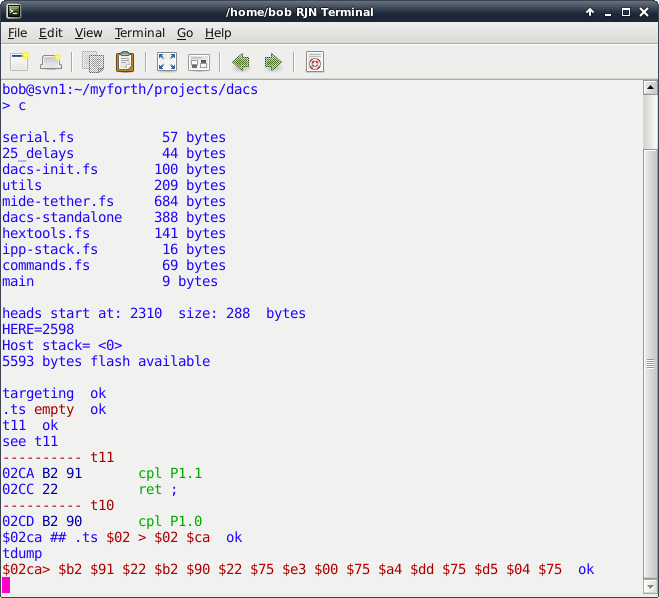
Photo 7. Application Testing on the Host
Page 33
You can download the MIDE source code (as a gzip tar file). The source code includes all of the scripts discussed above. The scripts pertaining to the pt directory on the Pi are in the pt subdirectory.
Also in the MIDE directory is a backups directory containing empty directories named "backup", "backup1", "backup2" and "backup3." These are part of a simple multi-level backup scheme implemented with the bak.sh script. Also in the backups directory is a temp directory for use with the cya.sh script. The bdiff.sh script performs a diff between selected files the current directory and the backup directory. You can ignore these scripts and directories (or not).
The c.sh scripts for both the mide and pt directories set values of 1 and 3 for "com?", respectively. These values establish the correct serial device.
Presently, for com?=1, the serial port is mapped to /dev/ttyUSB0 . For com?=3, the device is mapped to /dev/ttyAMA0, the device mapping for the Pi. These device designations may have to be changed for your configuration. Figure 11 shows the current mapping (the Pi mapping to /dev/ttyAMA0 is probably ok).
   \ a list of four strings
   here ," /dev/ttyS1"    ( com?=4)
   here ," /dev/ttyAMA0"  ( com?=3)
   here ," /dev/ttyUSB1"  ( com?=2)
   here ," /dev/ttyUSB0"  ( com?=1)
   create 'portnames   , , , ,
Figure 11. Serial Port Mapping in serial-linux.fs
The contents of the mide directory are almost identical to that of the prog-850 directory used for the PROG C2 programmer. The main difference is that the tethering extensions are loaded in the job file. The tethering code is contained in the mide-tether.fs source file.
You can also download the source for the dacs application (as a gzip tar file). This may be useful as a starter application but be forewarned that the application, although functional, is in the early stages of development. The dacs directory also contains folders for the simple backup scheme and various utility scripts, as described above.
The dacs application includes a standalone interpreter that is more suited for user interaction than the one used for the mide programmer (e.g., there are echos and prompts). A sample .bash_aliases file is also included in the dacs directory.
The word "a12" in the dacs application reads a 12-bit analog value on Port 1, Pin 2 (P1.2). If the Target is an 850 Toolstick daughter card, the P1.2 analog input connects to pot R10 on the Toolstick board.
The required analog initialization is in analog.fs and init.fs. The port is set up to use an input gain of 0.5 and the internal 1.65 Volt reference. Thus, the full scale value is 3.3 Volts (power supply voltages larger or smaller than two times the reference voltage may affect accuracy)
The dacs interpreter also recognizes the words th (temperature in hex) and td (temperature in decimal). These read the raw ADC count for the chip's on-board temperature sensor. The words mtd and mth display 10 consecutive temperature readings separated by 1/4 of a second.
Page 34
Initial Release |
||
First "production" release. |
||
Cleaned up analog source code, added 13-bit resolution and temperature words. Also added ".sh" to shell scripts to reflect current practice. |