For those following my many articles, you know that I have a solar powered web server that provides power for my ham equipment as well. I now have over 8 years of data and the system is still working very well. The cost was steep at the time, about $3K, most of that was for the three very large batteries. As time went on, I figured it turned out to be a very big bit of overkill and I could have used a cheaper and smaller system.
I frequent Harbor Freight and buy the occasional tool, knowing that some of their tools break after one use. I must say that most tools I bought have lasted much longer than that. However, they do sell a 45W solar panel kit that varies in price between $149 and $189. Last weekend it was down to $139 and I felt it was time to see what they really were selling. I did download the manual first and saw that the controller has a USB 5V connector that would power the BeagleBone nicely. So I bought the unit, which weights a lot more than I thought it should (45lbs), and started doing this article.
It comes without battery and you must get one for it to work correctly. I first though of using a lawn tractor battery, they are 12V and typically are 8 to 10AH rated, while costing about $30 to $40 each. That works out to about 120 Watt Hours (WH) and my needs are pretty close to that. A problem with low maintenance batteries is they still need maintenance and can emit gases. My solar system batteries are AGM or GEL type cells. These are competely sealed, non-vented, and have the electrolyte in the form of a GEL. I priced some of the AGM/GEL batteries used in wheelchairs and security systems and opted for a 12V/35AH battery for $65. A little higher priced than I wanted, as I was trying to be under $200 for everything, but the unit seemed to be a good compromise between capacity and price. Units costing $10 less were half the rating, while the next step up was almost double the price. The kit's documents list a HF part number 68680 as a universal battery to use. While I didn't remember seeing any batteries in the store, I later discovered that most stores carry it, packaged in a box, and it normally sells for $69. If you use one of your 20% off coupons, the price will be lower than most internet prices, while their normal price is typical.
I now have what I think will be all the needed parts still in their boxes. My design calls for following their instructions and using some monitoring tools to see how well it all works and if there are any problems.
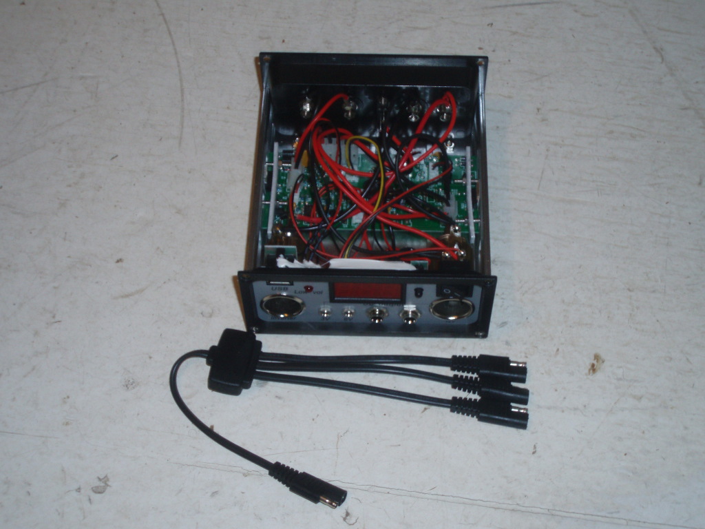
The first step then is opening the "kit" and seeing what is there. While the whole package weight was 45 lbs, the individual parts seems much lighter. The cells are about 5 lbs each, frame about same, and controller a litle less. The cables are a bit light for my tastes - .75mm2 or about AWG 19, which is max for about 3Amps, the typical max you might see. The connectors for attaching to the battery are just clamps and will need replacing with actual connectors. I would suggest using the cables from the cells to the controller that are supplied, but use larger cabling, say - stranded AWG14, for the controller to the battery, as you could draw more current than they are rated for. For items like ham radios, you should connect directly to the battery.
The kit includes a charge controller, which has USB charge socket and is one of the reasons I wanted the unit. The USB socket will be used to power the BeagleBone. I searched the web and found some interesting reviews, several of which said using the included charge controller may harm your battery. Now there are several things to keep in mind about what and how charge controllers are suppose to work. Simple charge controllers, which the documents lead you to think this unit is, mainly keep the battery from being over charged and shutting the system down if the voltage drops below some set point. The clearly poorly worded and written manual, typical of HF manuals, would lead one to conclude the charge controller has no charging software designed for normal solar batteries. To explain - different types of batteries have different charging rates and points where the charge rate needs to change, including different max voltages.
When we look at the charge controller we do not see any means of changing how it charges for different batteries. Therefore it is desinged to work with one type of battery, and the quick guide suggest we use the HF 68680 battery, which just happens to be a AGM/GEL battery. I found several reviewers who used that battery and stated they had no problems even after several years of use. The manual says the controller will shut off the unit if the battery voltage excedds 14.5V, which seems right for a AGM, although I need to research it again to make sure my mind isn't just getting too old to remember correctly. So my bottom line and for this testing round, I will assume the controller is OK to use for AGM batteries until I learn otherwise. I will open the controller as well to see if anything can be found out inside other than what the 4Amp fuse actually controls.
You might wonder why I am interested in figuring out what the 4Amp fuse controls, but keep in mind there are several ways to use the controller. First off the controller needs to "throttle" the output of the solar cells to not exceed the maximum voltage or current of the system. Secondly it must limit the voltage applied to the battery and not exceed the charging rate, as exceeding it will over heat the battery and damage it. Lastly it must make sure that devices connected to the controller, such as our BeagleBone are not damaged from over or under voltage. So typically there are three voltage paths if you will, each with their own concerns. However, you normally would connect heavy loads, such as ham gear, directly to the battey, where short peak draws can well exceed the controllers ratings. In those cases the controller really is being used simply to charge the battery. I plan to use and montior both the normal load from the controller and extra loads applied to the battery over time.
It all came out of the box with no problems and seems well protected for shipping. The manual is typical of HF - very poor and rather limited. Searching the web reveals nothing, as the units are made for HF under some funny agreement that makes it pretty hard to figure out who actually makes what for them. You might guess this is one of the reasons I am not a supper fan of HF stuff. The product seems like it will do the job, but I can't find any real facts to know for sure. A simple problem will show you what I mean. The controller diagram shows that the left hand lighter socket is for the "inverter" while the right hand socket is for 12V output. I suspect that both are actually just 12V output sockets, but one can't be sure without seeing the schematic. The two 12V plugs for the lights - are they limited in current or all the combined loads limited to 4Amps? Is the 5V USB charge current 500MA, 1Amp, or 2 Amps? These are all very important facts that need to be understood when designing the load usage and how one uses the whole system.
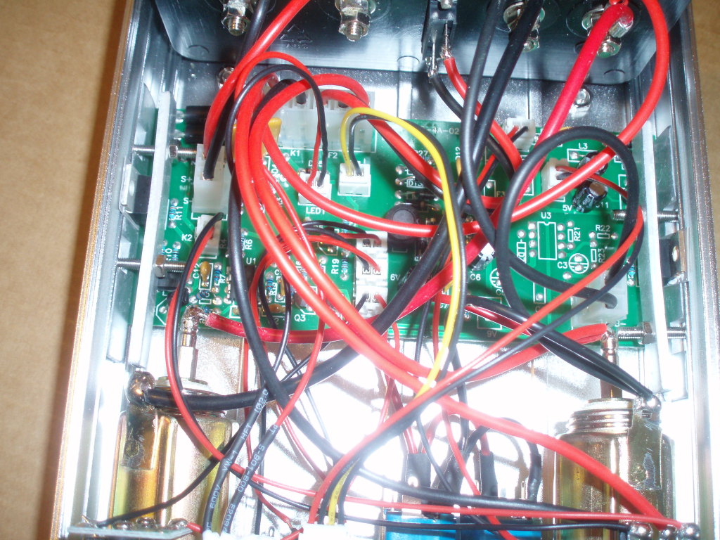
Well I opened the unit and saw that circuit board was labeled as TPS-545-A4-02 and did a search. Found the schematic and have included it with this article. In reviewing the schematic and looking at the actual wiring - see photo - I can see that the inverter connector is connected directly to the battery terminal. That means the inverter socket has no limits of any kind and you could easily exceed the 3 amp rating of the socket. I have had issues where these sockets that have gotten very hot when pushing the 3 amp limits, so beaware, they will not handle large loads. This also means the cabling to the controller from the battery should be larger than what is provided, especially if you use the inverter socket.
All the other sockets are conected to the 4Amp fuse on the back of the unit and as such must not exceed that limit when combined. The 6V and below are connected to a 1.5Amp device and as such their combined rating is 1.5 Amps. I don't really like the way their voltage is obtained - the regulator output is 6V, and the 5V is derived from the 1V drop accross a diode - no regulation at all. We get 3V by adding 3 more diodes from the 5V line. Total draw for all the output is 1.5 amps, which is not really too great, as some USB devices will draw up to 2 amps and thus not an option. So care will be need when using the lower voltages for both current usage and concern over regulation.
Let me say there is one item I like very much - the 12V cable connectors. These are the polarized plug/socket connectors from the cells and the combiner. I dislike the fact that the output wire size of the combiner is really a bit small, but then you should not be exceeding the ratings and some reviewers have said the units degrade quickly and thus you will not be able to get full output after a few months anyway. I will be testing that aspect to see if it is true or not. The connectors used are readily available at most auto stores and as such making longer cables would not be a problem. For my testing, only the battery cable will need replacement, everything else will be used as provided. The cables are 12 feet long on the cells, with the cable from the combiner to the controller being 16 feet. It is nice to have such long cables, but if the current gets high you will have losses at those length. Plan on getting your own cables and connectors, the extra wire material will be a good investment. Try AWG 14 for 10 to 20 feet and AWG 12 for anything longer.
I need to make sure that everyone understands OHMs Law. I have seen enough reviews to know that a number of the reviewers have no knowledge of electricty, and especially as it relates to wire size, resistance and voltage. When using the normal 110VAC of house wiring, a 60 watts lamp will draw about a half amp. However that same 60 watts when done using 12V will be 5Amps. Now a size 18 wire at 110 VAC will be just fine for the 60 watt lamp, however that same wire will be a bit small and might even get very hot when used at 12V and 60 watts. Remember this unit is rated at 45 Watts and thus the maximum current is less than 4 amps. If you add more, all the wire sizes will be somewhat under sized. Making the length of the wire longer will add more resistance to the wire and increase the volatge dropped along the wire as well, not to mention that loss turns into heat. I have seen more than my share of wiring over the years that shows signs of having been rather hot from too much current. Most electrical house fires are started by overloading extension cords that were too small for the amount of load they were forced to handle. There are many sites on the web that will calculate the voltage drop for a given length of wire and load - use them. My rule of thumb is that any drop greater than 0.1V, you need a larger size of wire.
At this point I have covered what you get, how it goes together, and some inside information not available with the unit. Let me say that it pretty much met my expectation of something from Harbor Freight - usable but with limits. Let me do a pro - con report without having used it for several months. I will add more later as I get data from actual use and see if any concern mentioned on the web turn out to be true.
The pro side says your getting reasonable value for your money. If your usage is limited to running something like a BeagleBone and a few I/O devices, say less that 1 AMP total, then all the included items wll work fine for you. Add in the cost of their battery to the mix and you will be just over $200. Add the cost of the BeagleBone Black and one should be able to get a solar powered remote web server running for close to $300. For the ham operators this unit will work fine for emergency drills where you need to power a VHF/UHF radio during a daytime event. The solar panels and controller should provide enough power to meet your needs and size wise should all fit on a small cart.
For the con side of things, there have been reports of cells dropping more than 30% of their output after a year or two of use. I did see reports of some cell failures out of box, which is really not that unusal for HF products and for items from China. The really awlful thing is the manual and it's lack of facts. You really need to know that the inverter socket is connected directly to the battery and will not shut down on low voltage. You need to know as well that all the other 12V outputs go through the 4Amp fuse on the back, that some have used 10amp fuses successfully, and that when under or over voltage happens, those output will have their ground opened internally. Now this is important, as you need to know that you should not ground items attached to the controller to the battery ground. In my solar powered system, I return all grounds to a common point, batteries, devices, controller, everything runs to an external ground rod - we are talking safety here. I find opening the ground side of anything totaly unacceptable.
With all that in mind, your getting some good value here, especially if you can pick one up for $139 or $149. Just keep in mind the limits, it is really desinged for limited use and not powering anything big - the included wire sizes are way too small for anything big. What I need to do next is get some real data and that will take time, So stand by and come back in a few months to see how things are working.
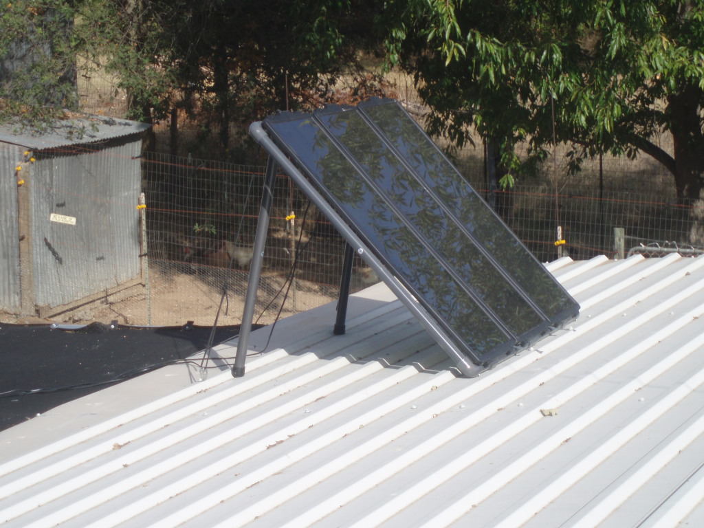
It has been a few months since I started the article and I was out of town for most of that time. When I got back, I mounted the solar array on the roof of my carport, a flat section that has the upward slanting part in front of the unit. This means I should get a bit more efficency out of the unit due to reflection off of the white metal roofing. However as it turns out there is no way for me to see that change. Let me explain.
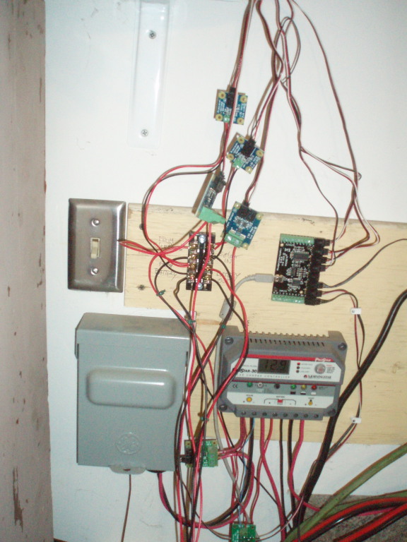
I have the unit setup and connected to my monitoring system that tracks the volts and amps to and from the larger solar system that powers the web server and ham gear. I added four new columns of data and you can see it here. What I noticed first was that the charging happens rather rarely since I only sample twice an hour. The charge seems to start when the battery drops below 13.2V and stop when it gets to 13.5V. This forced me to review the schematic and figure it all out. It seems there are two opamps that compare voltages and when lower than the setpoint - open or close the ground path. The closing happens when the battery drops below the setpoint and grounds the solar array negative connector, thus causing the battery to be charged. The opening happens when the volatge drops below the cutoff point and opens the ground path for things connected to the controller. Rembember that I find this whole concept totally unsafe and in fact you may prevent things working properly if you were to correctly gound everything as it should be.
Several previous web sites have suggested that one get a real solar controller and I would agree with that concept. Will this one work anyway - yes. It is now powering a BeagleBone and I am tracking what happens, and so far it seems OK. I am a bit concerned about the network connection, as it is probably providing grounding for everything - you really should use a wifi network connection to keep the system isolated from grounds. I can see that the charge never exceeds about 13.5V and thus should never overcharge the battery. Does it charge the battery correctly - for sure not. Will it kill the battery over time, I have my doubts, but can not be sure since it is basically under-charging it. will the battery last as long as it should? That one is hard to say, but mosty likely no since it is not properly charging it.
Another set of questions might be - is the voltages provided accurate - I haven't tested yet, but the BeagleBone seems to be working fine and thus they seems to close enough. The best way to be using this stuff, would be with a real controller, everything grounded properly, and real 12V to regulated output converters. Doing it that way breaks up the modules and allows for proper trouble shooting and monitoring. The HF way however works, just not for long term and reliable operations. The HF stuff really is intended for limited and portable operations where many of the concerns are not important. For long term and highly reliable usage - get something other than HF products.
Table of Solar Arrays output
HF charger schematic in PDF format.
Solar Controller and combiner
Insides of the solar controller
Solar Aray on carport roof
Phidgets controller and sensors on solar cables
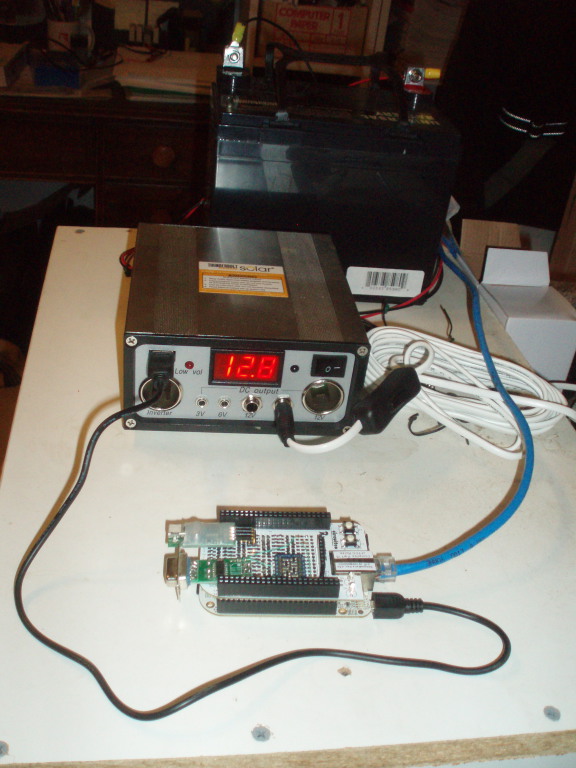
Battery, solar controller, and BeagleBone with homemade serial cape