We have recently developed a new product called the MINT processor. It is a very small 1 1/4" x 3/4" board wih an C8051F850 (850) chip, a regulator and all chip I/O brought out to edge pads. It intended use is as a small general-purpose processor for use in our labs. The new processor has been dubbed the "MINT" processor (MIni Target).
This note describes how to use a MINT to build a smaller version of the MIDE C2 programmer and interactive debugger described in the PROG Manual and the MIDE Manual.
The featured processor in these manuals is the Toolstick 850 board manufactured by Silicon Laboratories, Inc. (SL). The replacement programmer/debugger is about one third the size of the Toolstick-based programmer.
Other than reduced size there is nothing special about the new MINT-based programmer: the purpose of this note is primarily to show an example application for the MINT. The following refers to the new programmer/debugger as "PMINT" (programmer/debugger MINT).
The PMINT implementation is straightforward. The MINT processor board plugs into a small perforated board that acts as a motherbord for the MINT processor, the programming plug and three resistors. The power and serial I/O for PMINT are connected via the BOBI interface on the MINT. This makes it easier to connect power and I/O to the PMINT than the separate connecter required for the Toolstick-based programmer.
Page 2
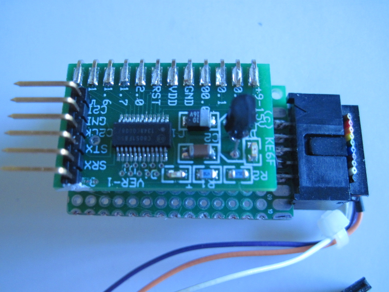
As shown in Photo 1, the heart of the PMINT is the MINT board that mounts parallel to its motherboard using a socket mounted on one edge of the motherboard. This parallel mounting requires the installation of a right angle connector on the MINT connector edge (a 2X12, 0.1 inch-spaced connector footprint). The photo shows the MINT board mated to a socket mounted along one edge of the 1.5 by 1 inch (38X25 mm) motherboard.
Schematic 1 shows the PMINT connections. Note that only three wires need be brought down to the motherboard from the MINT processor board: ground, P0.0 and P0.1. Also note that the PMINT power and serial connections are available on the BOBI connector.
The connector for the programming cable is a 2X5 IDC shrouded connector that mounts on the short end of the motherboard. The perforated board we used has solder "paddles" arranged on opposite sides of the board edge. This allows the connector to straddle the board edge. An equivalent mounting for standard perforated boards is to use a connector with right angle pins to mount on 0.1-inch spaced solder pads.
Not visible in Photo 1 are three resistors that mount on the motherboard, under the MINT board These connect between the the MINT socket and the programming socket, as indicated in the schematic.
The 2X5 programming plug can directly connect to any SL Target Board that uses a C2 programming interface. This type of connection simply requires a 10-pin ribbon cable to be connected between the Target and PMINT programming connector.
Photo 2 shows a more typical PMINT programming and debugging connection. In this configuration, the programming cable (shown in Schematic 1) connects to a DACS board through a BOBI breakout board. This provides all of the power, programming and interactive debug connections needed for project development.
Photo 2 also shows a power/serial cable from a Raspberry Pi (the brown, green, orange and red cable). The cable from the Pi connects to the MINT processor's BOBI interface through a small adapter board. This is just the programming configuration we use. Another alternative would be the use of dual-socket breadboarding wires installed from the MINT's BOBI connector to a USB to serial adaptor.
The Toolstick-based programmer is also shown in Photo 2 to illustrate its size relative to the PMINT. This was the processor used to load the MIDE firmware into the PMINT. The MIDE Manual discusses the firmware, how to download it and its usage.
We can furnish MINT processors pre-programmed with the MIDE firmware and tested in our programmer. We can also furnish complete, tested, PMINT units.
Page 3
Photo 1. PMINT C2 Programmer and Interactive Debugger
Page 4
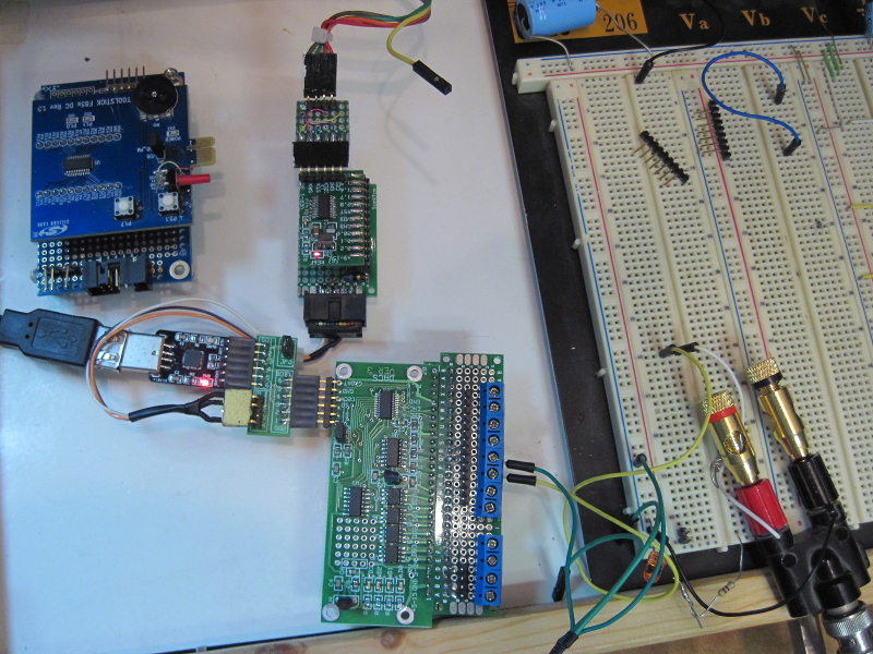
Photo 2. PMINT Connected to a DACS Board
Initial release |
Copyright © June 30, 2014, Bob Nash.