|
Industrial Support Since 1975 | |
|
Solar and Alternate Energy
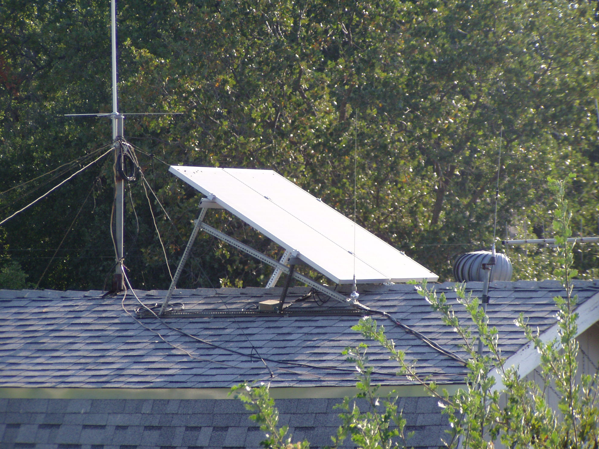
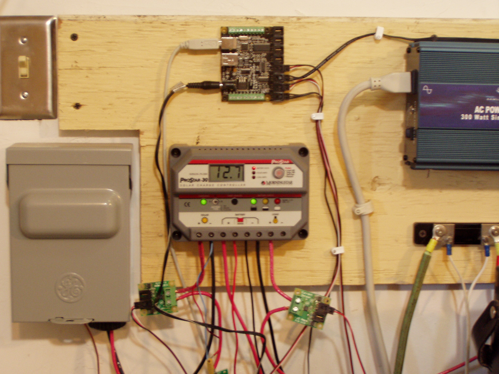
Back in the 70s I got into solar energy in a big way. Then I obtained a BA from Sonoma State University in Environmental Studies with an emphasis in Solar Energy. I studied all the basics of solar energy, solar house design, worked on numerous solar design projects and analyized ways to use solar to pump water. Part of understanding the use of solar, requires understanding all the aspects of house location, heat loses and gains. Well designed passive solar houses can benefit from active features such as shutters, fans, and venting systems. In the 70's those solar components were always manually activated, but not today. Today, houses use computers to control solar systems, and it was that concept of using computers that took me away from solar and got me into computers. Solar is also a source of power that can be used to power remote sites and emergency equipment. Kibler electronics is working on a number of products to support this area of communications and emergency services. In fact this site is completely run "off grid" - using batteries and solar collectors. Servers running 24/7 can cost as much as $50 a month, thus making solar powered servers cost effective over time. This site is Powered by Energy From the Sun This server is powered by a solar array and battery storage system. I have been running this solar system since early 2007 and it powers both ham equipment and this web server. The folowing will try and describe both the reasoning, as it relates to cost and overall features, and design from a practical view point. Let us start by reviewing my reasoning and a few calculations. My reasoning starts something like this - I am a ham radio operator, and have been one since early 1960. Most modern ham equiptment is powered off of 12 volts. To some extend that is due to mobile operations, that being from a car, yet many fixed station equiptment is 12 volts. Typically you use a power supply that converts 110 vac into 12 volts. There are many hams like myself who use solar and or batteries instead of power supplies. The main reason for many of us, is emergency operation when the power lines are down. From a cost stand point, I looked at my PG&E bill and can see that the current cost of the highest usage ( 200KWH and above ) is running $.40 a KWH. Having measured all my systems, I can see that a typical system is around 100W and will cost about a $1 a day to run. Laptops are in the 20 to 40w range, while big systems with large monitors can consume as much as 300 to 400w to run. So there are some cost assocaited with running servers 24/7 that solar could reduce. Your saving will vary, but 300 to $400 dollars a year is easy, while more complex systems might be costing you $1000 a year. It is not cheap currently to replace a simple 12 volt supply for some equiptment with a battery and solar array. My current system in 2007 was slightly over $2500 to put together. The server is now a Hitachi laptop that draws one to two amp from the batteries (12 to 20watts) The cost saving for a whole year is about $75, which makes the payback. period longer than the life of the system. So what were the design conditions that I used to overspend on the inital cost versus the saving I expected to get. There were two aspect of the design that setup the list of parts - mainly the overall power needs and how long I wanted to go without sun. As I said earlier, a typical system I was using at the time consumed about 100 watts and thus set my base power needs. The other concern was how long I could go without sun and in this part of California where I live, we rarely exceed 2 or 3 days without enough sun to do some recharging. Ideally I wanted a full week, but at the time I settled for 3 or 4 days. As you will see later my design has changed over time and I now have the flexibility to go a full week if needed.. The Design I settled on a design with two 115W solar panels, three 86AH batteries, and one 30A solar battery charger. In 2007 those items cost $1900, and I added some extra cable connectors, junction boxes, heavy wire, and special mounting rails, which added about $400 more for a total of $2300. The roof mounted two collectors and all the cabling has not changed from setup. I have adjusted the wiring for the batteries to make sure all are the same length, along with some adjustment to the load side to make sure the charge controller can see a load at all times. Those minor tweaks I feel helped the charge controller work better, but the effects were slight. One problem I had was most of my roof lines run north and south and thus a flat mount on the roof is not possible. I checked peformance using mounts on the two down slopes and decided instead to make my own rather ugly mounting as can be seen in this picture. This was shot from my house and shows the wifi antenna we need to use for the internet, since AT&T will not service remote areas with high speed internet. As I said, I made my own mounting hardware using perforated steel strips from Home Depot. You get a much better view of the structure in this view . The two panels are mounted on real solar mounting rails, with the proper fastening clips. The rails are atached to the perforated braces. You can see a junctionn box where the wires from the special connectors come together. Most current panels use special MC connectors that are rated at 600V as a typical house design will have the panels connected to provide around 400V to the inverter. You can find premade cables and connectors with pig tails for your own assembly - they are not cheap. In my office, which is just below the roof, the two #4 wires land in a fuse box, where I can disconnect the load from the panels. The panels are wired in parallel and can provide 15 - 18Amps maximum. I use 20A fuses for protection, and the units are grounded properly. The controller is connected to the fuse box for it's input, while the output goes to two bus bars for sticking wires under screw downs. Most of those parts were bought at the local Home Depot. The batteries use several length of standard battery cables and connect into the charge controller. My ham equiptment can draw more current on voice peaks than the charge controller can handle and thus, I use a MFJ-1124 connector panel connected directly to the batteries. This is one of the little changes that were made as I learned more about my load usage and how the charge controller worked. I was not looking for awards here, but functional design when I mounted all the components in my office on a piece of scrap plywood on the wall over my desk at the time. You can see the overall layout here, with a more closer view of the controller here. There are a number of items to discuss that appear in the pictures. Above the Charge controller is a Phidget Interface Kit that I was using to measure the input and output loads - currently broken. The black plastic bar and meter to the right is a 50Amp shunt combination to measure ham equiptment loads. In the large picture you can just see the edges of the MFJ and bus bar strips where I connect loads. Let me say here, I used the Anderson power pole connectors and found them totally unacceptable. The overall contact surface and design is just not adequate for #10 or larger wires, and they should only be put together using the approved tools. I prefer bus bars with screw down terminals ( what is in most household breaker panels) and have yet to have any work loose. Things don't last forever As part of my marketing plan for selling some addons for systems like mine, I wanted to make a low cost monitoring system with an ethernet interface and web server. The first part was to use some cheap voltage and current monitoring tools. What I found was the product Phidget. This product was developed as part of a college project and as such is cheap but with limited accuracy. I just checked and Trossen Robotics still sells the 8/8/8, although it looks a little different in the picture. It costs just under $80 and can provide 8 in, 8 out, and 8 sensors. I only use 4 sensors, 2 current and 2 voltage. I have a very accurate volt meter and found the sensor to be high, and ended up putting a trim pot in line with the signal to lower the reported value. I think the issue was load resistance of the sensor, as just touching the connection pins with the meter would change the reported value. As I said, it worked fine until a few months ago, when I discovered that not only the phidget device had failed, but I also used two single wire temperature sensor kits that read up to 4 sensor and one of which the pic chip had died. I was a bit bumed to have two sub devices fail in about the same time, so I did consider that it might be noise spikes that killed them. However the 12 volts from the batteries is rather clean and so not sure what could have happened to kill two devices. You do want to make sure your grounded properly, since solar arrays can get hit by lighting and see lighting caused spikes just like regualr utility power. Another topic to discuss is the use of inverters. I first got a modified wave inverter for testing and using to supply the many power bricks that items like switches use. Most of these small transformer based unit will work almost as well on modified sine waves as pure sine wave inverters. However, it seemed that a earlier model of the kill-o-watt meter, which I use for all my power usage testing, would burn up if used on anything but a pure sine wave. It seems they used some capacitor and resisitors to filter the sine wave and power the meter. The voltage output from a modified wave was considerably higher than designed and thus smoke was the typical results. In consdering the fact that I had little control over the transformers being compatible with modified wave output, I reconsidered and bouht a 300 watt pure sine wave inverter. It cost more, but then I don't have to worry about compatiblity and thus can just plug in devices as I see fit. What I would rather do is not use the wall transformers at all, but use standard 9-18 volt inverters that produce the desired DC voltage needed. They can run anywhere from 20 to $100 plus and be bought from any of the electroinc suppliers. The issue is how many you might need. It seems that no two devices use the same voltage, and in fact some are rather non-standard voltages. My wifi transformer is 24V at 400ma or about 10watts and when using the inverter, will pull a good solid 1 amp all the time. Reconsidering the Design I have started to reconsider many aspects of my design. Considering the number of little transformers that are powering the wifi, switches, and such, It might make more sense to power them from solar than the computer. I bought some 12 volt standard PC power supplies and quickly realized, it is better to just use a laptop than play with 12 volt PC power. Recently there have been tons of little arm pwered web serves, that draw as little as 4 watts. I just saw a ad for CVS pharmacy where they are selling a $99 netbook. These small arm unit are in the 5 to 7 watt range and would do very well as web and data collecting servers. It means that in many cases, the web server will be the least of your power needs, and thus other design layouts might be advised. I think I will repair my Phidget, because it did a good job of tracking my solar power, but I will look to make sure it is still the best deal for the price. My son's laptop developed screen issues, and thus I have it out of the case and was considering it as a new web server. The problem is power consumption, it draws around 20 watts, in stripped down mode. So I will either find an arm server, or power the transformers and run the server some other way - maybe as an VMware client on my workstation where it's 4 cpus can handle tons more I/O and processes. At this point I am reconsidering the design, the tools, and overall setup, to find the current best options. I am not sure what that will be, but it is fun trying to figure it out. Update - 11/25/2010 It is late November and I have run into a number of problems. My wife's web site is seeing plenty of new lookers, and some of my hardware systems failed the other day - taking the web pages off line. We live in the country and have no land-line type of internet connection, but instead use a wifi sytem that provides us with a connection to the internet. The download speeds are OK, but the upload is just way too slow for any large amounts of lookers to our web pages. I have been considering using an outside server for some time, and finally decided the time was now. I am now using the service "linode.com" and after providing my credit card number, had the web sites up and running within an hour. Actually it took longer to up load the web page data, than it did to setup the servers and move the DNS lookup IP to the new site. This should give much better service to our users and free up my systems while I fix a number of minor issues. As to the solar powered web site, I plan on changing the arrangement such that I use the new netbook (CCII_13) as a solar powered web server simulating a remote mountain top where it collects power and weather data. This will be a better design, since it separates my testing from producing real web pages. You will be able to read my articles no matter what stage of the changes I happen to be in. Further more it will be much closer to the real projects I have been trying to get going. Lastly, I will feel much better knowing my readers are getting information faster and without issues due to my hardware changes or problems. The updates about how things are going will be in Computer Corner Articles, so watch those pages for updates and more how-to articles. References
Phidgets from Trossen Robtics. |